Showing posts with label Battery Charger. Show all posts

Tuesday, September 7, 2021

Simple 12V battery charger with automatic charging indicator + PCB

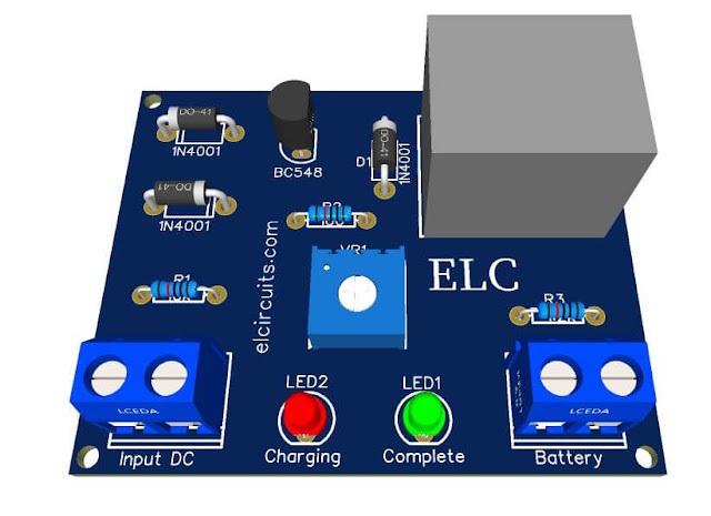
PCB - Simple 12V battery charger with automatic charging indicator

Para versão em Português, click aqui!

This is a Smart Battery Charger, with fully automatic 12V battery charge indicator. It is an extremely simple charger that anyone with little experience can assemble.

The input voltage depends on the power supply you are using, 110Vac or 220Vac. The charging time depends on the power supply you are using and the type of battery you are charging.

To calculate the closest charging time, we can do a simple and objective quick calculation that does not take into account the variations of the resistance factors of the battery, the variations of the charger, the chemical depreciation factor of the battery and so on.

You may be interested in: 

The calculation is quite simple. Let us take an example: you have a UPS 12 volt battery with 7 amps, your power supply is 3 amps

So we know that the battery charge is "more or less" 7 Amps Hour, which means that to fully charge the battery, 7 constant amps are required. Since the power supply is 3 amps, we need to divide 7 amps by 3 amps of power supply.

To charge a battery without damaging it usually requires a current of 10% and a maximum of 20% of its current. For example:

If our battery is 7 amps, the most we need is a 1.4 amp charger, and normal charging consumption is 700 milliamps. This 10% is normally used in devices that are directly connected to the power, such as alarm systems, backup devices and others.

Let's do the calculations using the formula

  • B = battery
  • PS = power supply
  • C = current

C = B / PS

C = 7/3 C = 2.33

Meaning:

Charge "C" lasts 2:33 hours

Two hours and thirty-three minutes to charge

If your PS is different, no problem, look at its supply current and put in the formula to see the approximate result.

Figure 2 shows the complete electrical schematic of the small circuit.

Fig. 2 - Electronic Schematic Simple 12V Automatic Battery Charger

It is important that the power supply delivers 20% more than the battery voltage, e.g. if your battery is 12 V, the power supply must be 14,4 V. You can vary a little, e.g. 13.2 V, "which is 10% of the battery voltage", but you cannot use a 12 V power supply to charge a 12 V battery as there will be no potential difference.

Here is how to use the charger:

When all the assembly is done, carefully check for wrong parts, reverse polarity diodes and shorts in the terminals after checking everything.

Connect the positive terminal of the power supply to the input of the +Vcc circuit and the negative terminal of the power supply to the ground circuit of the charger. 

With the potentiometer or trimpot you can regulate the output voltage of the charger, for example you have a 12V battery, normally 12V batteries UPS are charged at 13.2V at 14.4 volts.

Then use a multimeter on the DC volt scale, "it depends on the multimeter", on the output of the charger and set the voltage to the most desired, ie the maximum voltage for it to fire and the green LED will light up.

You can now use your new charger, insert the battery and let it charge until the charger reaches the voltage you set, "limit voltage", it will trigger the relay and turn on the green LED, indicating that the battery has been charged.

A good tip: If you have a spare 12v buzzer, or if you really want to add an audible indicator to your circuit, you can connect these buzzers, which you can easily find in electronics stores and are cheap, to the output where the green LED is lit, which is the full charge indicator, and you can turn on the positive buzzer on the relay output and the negative buzzer directly on the output.

Material List:

  • Q1..................... General purpose NPN transistor, C1815, BC548 etc.
  • D1, D2, D3 ...... Diodes 1N4001.
  • R1 ..................... Resistor 1/8W 10K (Brown, Black, Orange)
  • R2 ..................... Resistor 1/8W 100 Ohms (Brown, Black, Brown)
  • R3 ..................... Resistor 1/8W 1K2 (Brown, Red, Red)
  • VR1 ................. 10K Trimmpot or Potentiometer
  • P1, P2 ............... KF301 2 Pin 5.08mm Pitch Plug-in Screw Terminal Block Connector 
  • RL1 ................... Relay 12V 10A, 5 pins
  • LED1, LED2 .... 3mm LEDs, one Red and one Green
  • Others ............... Printed circuit board, soldering iron, tin, wire, etc.
We offer for download the necessary materials for those who want to assemble with PCI - Printed Circuit Board, the files in PNG, PDF and GERBER files for those who want to send for printing.

Download:


If you have any questions, suggestions or corrections, please leave them in the comments and we will answer them soon.

Subscribe to our blog!!! Click here - elcircuits.com!!!

My Best Regards!!!

Thursday, July 15, 2021

3.7V Li-Ion Battery Charger Circuit using MCP73831 IC + PCB

Fig.1 - 3.7V Li-Ion Battery Charger Circuit with IC MCP73831


The  MCP73831  device  is an advanced  linear charge  management  controllers  for  use  in  space limited, cost-sensitive applications. 

The MCP73831 is available in an 8-Lead, 2 mm x 3 mm DFN package or a  5-LeadSOT23  package.

Along  with  their  small physical size, the low number of external components required make the MCP73831 ideally suited for portable  applications.  

For  applications  charging  from  a USB   port,   the   MCP73831   adhere   to   all   the specifications governing the USB power bus.

The MCP73831 employ a constant-current and constant-voltage charge algorithm with selectable preconditioning  and  charge  termination.  

The  constant  voltage regulation  is  fixed  with  four  available  options:  4.20V, 4.35V,  4.40V  or  4.50V,  to  accommodate  new,  emerging  battery  charging  requirements. The  constant  current  value   is   set   with   one   external   resistor. 
The MCP73831 device  limit  the  charge  current  based on die temperature during high power or high ambient conditions.   

This   thermal   regulation   optimizes   the charge cycle time while maintaining device reliability. Several  options  are  available  for  the  preconditioning threshold, preconditioning current value, charge termination  value  and  automatic  recharge  threshold.  

The preconditioning  value  and  charge  termination  value are set  as  a  ratio,  or  percentage,  of  the  programmed constant  current  value.  

The  MCP73831  device  is fully a specified  over  the ambient temperature range of -40°C to +85°C.

The Circuit

The circuit is very simple and uses few external components which facilitates the assembly and reduces the assembly cost, the standard charging voltage regulation is normally set at 4.2V

However, there are variations in the nomenclature of the last digit of the IC that differentiate them from the standard charging voltage, such as:
  • MCP73831-2 = 4.2V
  • MCP73831-3 = 4.3V
  • MCP73831-4 = 4.4V
  • MCP73831-5 = 4.5V
The constant current charging value, is adjusted through resistor 2.2K ohms R3, which in our circuit is programmed for a ~450mA charge. Using a simple formula, we can vary this constant charging current:
Rc = charging resistor
CC = charging current in mA

Formula:
Cc = 1000/Rc

Being our 2.2K resistor, we have:
Cc = 1000/2.2
Cc = ~ 450mA

Remembering that the minimum charging current for this device is 15mA and the maximum current is 500mA.

Lithium-ion Batteries have become popular in large scale in portable electronic devices, due to them having higher energy density compared to other batteries on the market.

Benefits include thousands of recharges and none of the old, well-known “memory effect” problems we had in the first rechargeable NiCd battery cells

However, lithium-ion batteries must be charged following a carefully controlled constant current (CC) and constant voltage (CV) pattern that is unique to this type of cell.

Overloading and careless handling of a Li-Ion cell can cause permanent damage or instability and a potential danger of explosion.

In Figure 2 below, we have the 3.7V Li-Ion Battery Charger Circuit schematic diagram, with the MCP73831 IC and we can follow and analyze the entire circuit, which is a simple and easy-to-assemble circuit, with few external components.
Fig. 2 - 3.7V Li-Ion Battery Charger Circuit with IC MCP73831

Features

  • Linear load management controller:
  • Integrated pass-through transistor
  • Integrated current direction
  • Reverse Discharge Protection
  • High precision preset voltage regulation: +0.75%
  • Four voltage regulation options: 4.20V, 4.35V, 4.40V, 4.50V
  • Programmable load current: 15 mA to 500 mA
  • Selectable preconditioning: 10%, 20%, 40% or Disable
  • Selectable end of charge control: 5%, 7.5%, 10% or 20%
  • Three-state status output - MCP73831
  • automatic shutdown
  • Thermal regulation
  • Temperature range: -40°C to +85°C
  • Packaging: 5 derivations, SOT-23
  • applications
  • Lithium Ion / Lithium Polymer Battery Chargers
  • Personal Data Assistants
  • Mobile phones
  • Digital cameras
  • MP3 Players
  • Bluetooth Headphones
  • USB chargers

Components List

  • U1 ...................... Integrated Circuit MCP73831
  • LED1 ................. Light Emitting Diode - Red
  • LED2 ................. Light Emitting Diode - Green
  • R1, R2 ............... 240 Ohm Resistors
  • R3 ...................... 2.2K Ohms Charging Program
  • Others ................ Wires, connectors, PCI, tin etc.

The PCB - Printed Circuit Board

We are offering the PCB, in GERBER, PDF and PNG files, for you who want to do the most optimized assembly, either at home.

If you prefer in a company that develops the board, you can is downloading and make the files in the Download option below.

Files to download, Direct Link:

Click on the link beside: GERBER, PDF and PNG files

If you have any questions, suggestions or corrections, please leave them in the comments and we will answer them soon.

Subscribe to our blog!!! Click here - elcircuits.com!!!

My Best Regards!!!