Showing posts with label Linear Power Supply. Show all posts

Thursday, October 21, 2021

Adjustable Power Supply 1.2V to 37V, 6A, Short Circuit Protection using LM317 and TIP36 + PCB

Fig. 1 - Schematic diagram Adjustable power supply circuit with short circuit protection

Para Versão Original em Português, Clique Aqui!

This is an adjustable power supply circuit from 1.2V to 37V and 6 amps of current, with short circuit protection, equipped with adjustable positive voltage stabilization circuits of three terminals LM317, plus a booster circuit, using the TIP36C, which is an inexpensive power transistor.

What makes this power supply special is the implementation of a short-circuit protection circuit, for which a BD140 PNP transistor is used.

You may be interested in: 


How the circuit works

Resistor R1, which is a load sensing resistor, receives a small current flowing through it. As long as the current in the output circuit does not reach a certain current calculated through R1, the circuit behaves like a normal voltage regulator, because at small "calculated" currents there is no voltage drop in the load sensing resistor, so the Boosters TIP36C transistor does not trip.

As the current in the circuit increases, the voltage across resistor R1 increases. When this voltage reaches about 0.6 V, the "transistor cut-off voltage", the power transistors turn on and current flows through them, with the threshold determined by the maximum current supported by the power transistors.

However, we have implemented a current protection circuit that consists of a circuit equipped with a BD140 transistor with a resistor that acts as a current sensing resistor that serves to polarize the transistor and, depending on the value detected, limit the output current of the entire circuit according to a simple Ohm's Law formula that serves to set this threshold current.

Formula 1st Ohm's Law

The 1st Ohm's Law states that the potential difference between two points of a resistor is proportional to the electric current flowing in it, and that the ratio of electric potential to electric current is always constant for ohmic resistors. The formula is as follows: V = R * I
  • V - Voltage or electric potential
  • R - Electrical resistance
  • I - Electrical current

Knowing Ohm's Law, we can now calculate the values of the load sense resistors that activate the power stage and the bias resistors of the protection transistors that form the short circuit protection circuit.

Calculating the load resistors

First, we need to know the current of the LM317 voltage regulator, which is 1.5 amps according to the datasheet.

LM317 = 1.5A
Let us calculate R1. We know that using Ohm's law, we get the following expression:
  • V = R * I
  • V = The cut-off voltage of transistors Q2 and Q3 TIP36C is 0.6V. This is the cut-off range of the transistor. Let us call Q2 and Q3 of Qeq

I = This is the current of the regulator IC1. Let us set the operating current of IC1 to 600mA, which is 0.6A. This current is enough for the IC to work unhindered.

Then:

  • R1 = Vbe_Qeq / I_CI1
  • R1 = 0.6V / 0.6A
  • R1 = 1 Ohm

Calculation of the protection circuit resistance

Similarly, we need to know the total current of the selected power supply so that there is an interruption in this range. Our power supply for 6 amps.

Power supply = 6A
Let us calculate R2. We know that Ohm's law gives us the following expression:

  • V = R * I
  • V = The cut-off voltage of the transistor Q1 is 0.6 V. "This is the cut-off range of the transistor".
  • I = The total current of the power supply, which is 6A.

Then:

  • R1 = Vbe_Q1 / I_ps
  • R1 = 0.6V / 6A
  • R1 = 0.1 Ohm

Current of the power transistors

Q2 + Q3 = 25A + 25A = 50A

However, the total power of the TIP36C transistor is 125W, which means it operates at a current of 25A to 5V. Remember the above formula, P = V * I;
  • P = 5V * 25A = 125W.

For this circuit with a maximum voltage of 37V and transistors with a maximum power of 125W, we look as follows:
  • Pmax = V * I:
  • Imax = P / V = > Imax = 125W / 37V = > Imax = 3.37A
  • How are two transistors together Imax = 6,74A

Therefore, our circuit works with two TIP36C transistors to get 6 amps at the output.

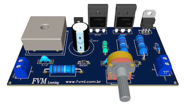
Figure 2 shows the schematic of the adjustable power supply circuit with short circuit protection. Those who follow us already know this circuit very well, the difference is exactly in the implementation of the protection circuit, as we can see below.
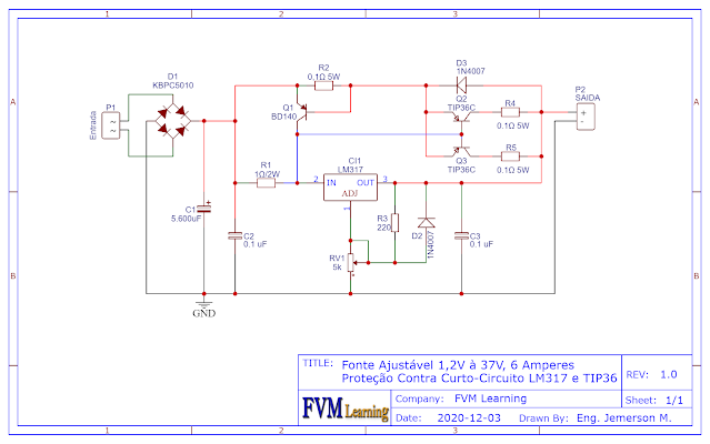
Fig. 2 - Schematic diagram Adjustable power supply circuit with short circuit protection

Components List

  • CI1 ................ Voltage Regulator LM317
  • Q1 ................. PNP Transistor BD140
  • Q2, Q3 .......... Power Transistor PNP TIP36C
  • D1 ................. Bridge Rectifier 50A - KBPC5010
  • D2, D3 .......... Rectifier Diode 1N4007
  • R1 ................. Resistor 2W / 1Ω
  • R2, R4, R5 ... Resistor 5W / 0.1Ω
  • R3 ................ Resistor 1/4W / 220Ω
  • C1 ................ Electrolytic Capacitor 5600uF - 50V
  • C2, C3 .......... Polyester/Ceramic Capacitor 0.1uF or 100nF
  • RV1 .............. Potentiometer 5KΩ
  • P1, P2 ........... Screw Terminal Type 5mm 2-Pin Connector
  • Others .......... Wires, solders, printed circuit board, etc.
Source: fvml.com.br

Download

We provide the files with the PCB, the schematic, the PDF, GERBER and JPG, PNG and provide a direct link for free download and a direct link, "MEGA".

Click on the direct link to download the files: Layout PCB, PDF, GERBER, JPG

If you have any questions, suggestions or corrections, please leave them in the comments and we will answer them soon.

Subscribe to our blog!!! Click here - elcircuits.com!!!

My Best Regards!!!

Wednesday, August 4, 2021

Symmetrical Adjustable Power Supply 1.25V to 47V 10 Amps with Short Circuit Protection + PCB


Fig. 1 - Symmetrical Adjustable Power Supply 1.25V to 47V 10 Amps with Short Circuit Protection  
This is a Symmetrical Adjustable Power Supply can vary its output voltage from 1.25V to 47V, based on the LM317HV Linear Voltage Regulator Integrated Circuit for positive voltage and the LM337HV for negative voltage, which together with the NPN transistors TIP 35C and the PNP transistor TIP36C provide a current of 10 amps.

This schematic was taken from our partner fvml.com.br, what we did was a small change in the supported current capacitance, you can check the original circuit here Click Here!

High Voltage Adjustable Regulator

The LM317HV and LM337HV voltage regulators are adjustable 3-terminal voltage regulators capable of delivering currents of 1.5A or more over an output voltage range of 1.25V to 50V

The LM317HV and LM337HV offer overload protection such as current limiting, thermal overload protection, and safe-area protection, that make the device breakdown-proof. The overload protection circuit remains fully functional even if the setting terminal is disconnected.

Remember, we limit the maximum output voltage of the power supply to 47V, because the LM337HV negative voltage regulator supports a maximum of 50V, unlike the LM317HV which supports up to 60V.

How the Circuit Works

After rectification and filtering, which are the first basic operations of the circuit, the total voltage coming from the transformer and rectified enters the first output block, the voltage regulator, which is controlled by the LMs Integrated Circuit and mirror image "Same function, just in a negative way".

R1 and R2 are 10 ohm resistors that have the function of Load Sensor, they receive the current flowing through the circuit, and while this current does not reach the current calculated across the resistors R1 and R2, the circuit behaves like a normal voltage regulator, because for small "calculated" currents there is no voltage drop across the Load Sensing resistor, so the Boosters Transistors TIP36C and TIP35C are not activated.

When the current in the circuit increases, the voltage across resistor R1 increases, when this voltage reaches about 0.6V "transistor turn-off voltage", the power stage is activated and current flows through it.

The Protection Circuit

The output short circuit protection circuit is formed by transistors; Q1 BD140 PNP and Q2 BD139 NPN, each for an output bias voltage.

They regulate the maximum current "Calculated", which is fixed at 10 amps, and work together with 0.06ohm resistors R3 and R4 as a current sensing resistor, which is used to polarize transistors Q1 and Q2, so that, depending on the determined value, they limit the output current of the entire circuit according to a simple formula from Ohms Law, which is used to set this limiting current.

Formula 1st Ohm's Law

The First Ohm's Law states that the potential difference between two points of a resistor is proportional to the electrical current established in it, and the ratio of electrical potential to electrical current is always constant for ohmic resistors. The formula is given by: V = R * I

V - Voltage or Electrical Potential
R - Electrical Resistance
I - Electrical Current

Armed with the knowledge of the ohms law, we can now calculate the values ​​of the Load Sense resistors, which activates the power step, and the bias resistors of the protection transistors, which is the Short Circuit protection circuit.

Load Resistor Calculation

First, we have to know the current of the LM317hv Voltage Regulator, which according to the datasheet is 1.5 amps.

LM317HV & LM337HV = 1.5A
Let's calculate R1, knowing that the same calculation is done for R2. We know that Ohm's Law gives us the following expression:

V = R * I
V = The cutoff voltage of transistors Q3, Q4 & Q5, which follows the same principle for set Q6, Q7 & Q8, is 0.6V "Which is the Transistor cutoff region". Let's call Q3, Q4 & Q5 as a Qeq.

I = It is the current of the regulator CI1, let's put the working current of the CI1 at 300mA, which is equal to 0.3A, with this current we won't need to put a heatsink on it.

Then:

R1 = Vbe_Qeq / I_CI1
R1 = 0.6V / 0.3A
R1 = 2 ohms

Protection Circuit Resistor Calculation

Likewise, we have to know the total current of the chosen source so that there is a cut in this region. Our source is for 10 Amps.

Power Supply = 10A
Let's calculate R3, knowing that the same calculation is done for R4. We know that Ohm's Law gives us the following expression:

V = R * I
V = The cutoff voltage of transistor Q1, which follows the same principle as for transistor Q2, is 0.6V "Which is the Transistor cutoff region".

I = It is the total current of PS, which is 10A.

Then:

R1 = Vbe_Q1 / I_ps
R1 = 0.6V / 10A
R1 = 0.06 ohms

Power Transistors Current

Q3 + Q4 + Q5 = 25A + 25A + 25 = 75A

NOTE: Remembering that the power of TIP36C transistors is 125W, this means that it works with current from 25A to 5V, remember the formula above, P=V*I;

P = 5V * 25A = 125W.

For this circuit with a maximum voltage of 47V, and transistors with a maximum power of 125W, we look like this:

Pmax = V * I:
Imax = P / V => Imax = 125W / 47V => Imax = 2.66A
How are three transistors together Imax = 7.98A

And that's why our circuit uses three TIP36C transistors to achieve 10 amps at the output.

In Figure 2 we have the schematic diagram of the adjustable power supply circuit with short circuit protection, so those who accompany us already know this circuit very well, the difference is exactly the implantation of the symmetry of the circuit and the protection circuit, as we can see below.
Fig. 2 - Symmetrical Adjustable Power Supply 1.25V to 47V 10 Amps with Short Circuit Protection

The Power Transformer

The transformer must be symmetrical, i.e.: "3 wires". The transformer must be able to supply at least 10A at the output. The primary, "input voltage", must match the voltage in your area; 110V or 220Vac. The secondary, "output voltage" should be 36 - 0V - 36Vac.

Component List

  • Semiconductors
    • U1 ....................... LM317HV Voltage Regulator 
    • U2 ....................... LM337HV Voltage Regulator 
    • Q1 ....................... PNP BD140 Transistor 
    • Q2 ....................... NPN BD139 Transistor 
    • Q3, Q4, Q5 ......... PNP TIP36C Power Transistor
    • Q6, Q7, Q8 ......... NPN TIP35C Power Transistor 
    • D1 ...................... KBPC5010 - 50A Rectifier Bridge
    • D2, D3 ............... 1N4007 Diode Rectifier 

  • Resistors
    • R1, R2 ................ 2Ω / 2W  Resistor 
    • R3, R4 ................  0.06Ω / 5W Resistor 
    • R5, R6 ................ 5KΩ  / 1/8W Resistor 
    • R7, R8 ................ 120Ω / 1/8W Resistor 
    • R9, R10, R11 ...... 0.1Ω / 5W Resistor 
    • R12, R13, R14 .... 0.1Ω / 5W Resistor 
    • RV1 .................... 5KΩ Potentiometer 

  • Capacitors
    • C1, C2 ................ 5600uF - 63V Electrolytic capacitor 
    • C3, C4 ................ 10uF - 63V Electrolytic capacitor 
    • C5, C6 ................ 1000uF - 63V Electrolytic Capacitor

  • Others
    • P1, P2 ................. Connector 3 screw terminal 5mm 3 Pins
    • Others ................. Wires, Solders, pcb, etc.

We offer for download the necessary materials for those who want to assemble with PCI - Printed Circuit Board, the files in PNG, PDF and GERBER files for those who want to send for printing.

Download:


If you have any questions, suggestions or corrections, please leave them in the comments and we will answer them soon.

Subscribe to our blog!!! Click here - elcircuits.com!!!

My Best Regards!!!

Thursday, April 8, 2021

Adjustable Power Supply 1.2 to 37V High Current 20A using LM317 and TIP35C + PCB

Fig. 1 - PCB Adjustable Power Supply 1.2V to 37V - 20A


For Portuguese version, click here!

This is a High Current Variable Power Supply circuit, which works smoothly *With 20 Amps. And we will use the old, wonderful, and well-known LM317, which is an Integrated Circuit regulating positive variable voltage with a range of 1.25 to 37V, and 1.5 Amps.  

We obtained this circuit from our partner FVM Learning, which made it available to us, we made few changes, such as increasing the transistors that they speak of in the Original Post, and we made the PCB that was not available until now, the rest is exactly the same.

To make an appropriate Power Supply, it is necessary to have a current well greater than 1.5A, so that’s where the power transistors come in, they’re going to increase the current without varying the voltage.

Because this variation function is up to the LM317, and the current factor is up to the transistors that in this circuit we’re going to use TIP35C.

Circuit Operation

The LM317 is a variable positive voltage regulator, which is responsible for varying the output voltage and delivering the base of the power transistors to this variable voltage. 

Which together with the other transistors form a high current booster, and which depending on the amount of transistor and the sum of the currents of each transistor, we form a high current variable power supply.

The voltage that comes from the power supply enters directly into the TIP35C collector, and is controlled by varying the input voltage at the base. 

And in turn the voltage that will come out of the emitter, will be directly related to the control of the output voltage of the LM317, it is necessary to use a heat sink, as this holding energy is converted into heat.

The TIP35C is a High Power Mospec transistor, with a 25A continuous collector current capacity, thus making it the perfect transistor for this project.

* It is worth remembering that this transistor has a total power of 125W, that means that following the Ohms Law, the current was calculated by the manufacturer for this transistor at 5V, let's check:

Ohms Law Formula: P = V * I

P = Power: V = Voltage: I = Current:
I = P / V ==> I = 125/5 ==> I = 25A

In our case where the power supply will go up to 37V, we can consider that:
I = P / V ==> I = 125/37 ==> I = 3.38A

Did you see the difference? We put two transistors for this work, but if you are going to use this source continuously with the maximum voltage and total current, you will need to add two more pairs in this circuit. 

We can use this power supply with these parameters; Voltage, Current, maximum, but for continuous use, it will overheat the transistors and burn.

The TIP35C has 100V of Vce and Vbe, Emitter Collector Voltage, and Base Collector Voltage. Remember this, these settings refer to the TIP35C, there are other variants such as: TIP35 = 40V, TIP35A = 60V, TIP35B = 80V and TIP35C = 100V, so for this project you can use the TIP35C for greater efficiency.

The Adjustable Power Supply schematic diagram is shown in Figure 2, which shows the arrangement of the components and their connections to proceed with the assembly, which in the general context, is quite simple to assemble, and demonstrates a great effectiveness.

Fig. 2 - Schematic Diagram Adjustable Circuit - 1.25V ~ 37V, 20A CI LM317 and TIP35C

Components List

  • U1 ............................ LM317 voltage regulator integrated circuit
  • Q1 to Q6 .................. TIP35C Power Transistor
  • D1, D2, D3, D4 ....... 1N4007 Silicon rectifier diodes 
  • C1 ............................ 4700uF - 63V Electrolytic capacitor 
  • C2, C3 ..................... 0.1uF Ceramic / Polyester Capacitor 
  • R1 ............................ 220 ohms 1 / 4W Resistor - (red, red, brown, gold)
  • R2 ............................ 10K ohms - 1/4 W Resistor - (brown, black, orange, gold)
  • R3 to R8 .................. 0.22 ohms - 5W Resistor - (red, red, silver, gold)
  • P1 ............................ 5k ohms Potentiometer 
  • J1, J2 ....................... PCB Terminal Blocks - EK500V-XXP 20A - or equivalent
  • F1 ............................ PCB Fuse Clip Cartridge 250V 30A With Fuse 20A
  • Others ..................... Wires, Welds, Posts, PCB, Etc.

For those who want to download materials such as the schematic diagram in PDF, PCB Layout,  GERBER and JPG, we are providing a direct link to download all the material.

Direct link to download

Click in the link  to download the Files: PCB Layout, PDF, GERBER, JPG

If you have any questions, suggestions or corrections, please leave them in the comments and we will answer them soon.

Subscribe to our blog!!! Click here - elcircuits.com!!!

My Best Regards!!!

Sunday, March 21, 2021

Adjustable Power Supply 1.25v to 57V, 6 Amps using TIP36C + LM317HV + PCB

The LM317HV is an adjustable 3-terminal positive voltage regulator capable of supplying 1.5 A or more currents over a 1.25V to 57V output voltage range. It requires only two external resistors to set the output voltage. The LM317HV is packaged in standard transistor packages that are easily mounted and handled.

However, the LM317HV supports high voltage, but the current is still low, only 1.5A, our circuit, we are increasing a drive circuit to increase the current we need to 6 Amps, with three TIP36C transistors, which provides an adjustable output voltage between 1.25v to 57 volts, with a current of 6 Amps, which is enough for a bench power supply.

The Circuit

The schematic electrical diagram, which follows in Figure 2 below, it's very simple, first one, we have the voltage input that comes through connector J1, which enters through resistor R1, that as long as there is no current greater than the one calculated, there is no drop of voltage in R1, more if the current increases, there will be a voltage drop of approximately 0.6V, which will cause the transistors to saturate, causing the current to pass through the power transistors.

The capacitor C1 has the objective of attenuating the interference of the ripples and their stability. Capacitor C2 has the function of eliminating high interference, and capacitor C3 has the function of constancy to decrease the ripple and stability of the power supply. 

P1, is a 5K analog potentiometer, if you don’t have 5K you can put 4.7K, which is more commercial, the diodes D1 and D2 are to avoid reverse voltage over the Integrated Circuit U1, and in the transistors, resistors R3, R4 and R5, are impact resistors, which attenuate the difference between the transistors and prevent one from working more than the other.
Fig. 2- Adjustable Power Supply Schematic LM317HV + TIP36

Components list

  • U1…………….... LM317HV – Integrated circuit, voltage regulator
  • Q1,Q2,Q3 ...…... TIP46C Power Transistor
  • D1, D2 ………....1N4007- Silicon rectifier diodes
  • C1 ……………... 470 uF – 65V – Electrolytic capacitor
  • C2 ……………... 100 nF  Ceramic capacitor
  • C3 ……………... 2200 uF – 65V – Electrolytic capacitor
  • R1 ……………... 10 ohms – 1W – brown, black, black, gold
  • R2 ……………... 2K ohms – 1/4 W – red, black, orange, gold
  • R3, R4, R5 .….... 0.22 ohms – 5W – red, red, silver, gold
  • R6 ……………... 220 ohms – 1/4W – red, red, brown, gold
  • P1 ……………... 5 K ohms or 4,7 k ohms – Linear potentiometer
  • J1, J2 …….……. Kre Block Terminal Terminal 2-Way Double Connector
  • Others ............… Printed Circuit Board, tin, wire, etc.

We are offering to Download the link with the printed circuit board printing files, they are; Gerber, PDF layout, PNG, all the files with a direct link to Mega.

Direct link to download

Click in the link below to download the Files: PCB Layout, PDF, GERBER

If you have any questions, suggestions or corrections, please leave them in the comments and we will answer them soon.

Subscribe to our blog!!! Click here - elcircuits.com!!!

My Best Regards!!!

Saturday, February 6, 2021

Adjustable Power Supply 1.25v to 33V, 3 Amps using LM350 + PCB

Fig. 1 - PCB Power Supply LM350

Nowadays it is very important and necessary to have a bench power supply to test ours; projects, electronic circuits, to maintain equipment, among others. However, this power supply must have at least a voltage adjustment control, and at least a short circuit protection.

And this is the proposal of this circuit, a simple and very effective circuit, with protection against short circuit, and that brings in its output an adjustable voltage between, 1.25v to 33 volts, with a current of 3 Amps, which is enough for most of the projects, and still, this PS has protection circuit against short circuit and over-temperature protection.

You may be interested in: 

The LM350 Integrated Circuit

The LM350 IC is an adjustable three-pin positive voltage regulator capable of delivering 3.0 Amperes in an output voltage range of 1.2 V to 33 V. This voltage regulator is exceptionally easy to use and requires only two external resistors to adjust the output voltage.
Besides:

  • Internal Current Limiting
  • Thermal shutdown
  • Secure Area Compensation

What do the LM350 integrated circuit, an essentially explosion-proof component.
The LM350 serves a wide variety of applications:

  • Static Voltage Regulator for digital circuits
  • Stable Current Regulator
  • Variable Current Regulator

This device also does an especially simple adjustable switching regulator, a programmable output regulator, or connecting a fixed resistor between the setting and the output, the LM350 can be used as a precision current regulator:

  • Guaranteed 3.0 The output current
  • Adjustable output between 1.2 V and 33 V
  • Load Regulation Normally 0.1%
  • Line Regulation Normally 0.005% / V
  • Internal thermal overload protection
  • Temperature Short-Circuit Internal Current Limiting Current
  • Compensation of the safe area of the output transistor
  • Floating Operation for High Voltage Applications
  • Standard 3-way Transistor Package
  • Eliminates Socks Many Back Fix

The Circuit

The electric schematic diagram, it follows in Figure 2 below, is quite simple, first, we have the rectifier diode bridge KBL610 that is a bridge of 6 Amperes to 1000 Volts, however, you can use anyone that you have and that is above 4 Amperes over 50 Volts.

Diodes D2 and D3 are for the protection of the IC LM350, against short circuits, because when we start the Power Supply, and the capacitor C3 is totally discharged, and it becomes as a short-circuit for the IC.

The C1 capacitor is to attenuate the ripples interference and stability of the same. The C2 capacitor has the function of constancy to decrease Ripple, and stability of the power supply. 

P1, is an analog potentiometer of 5K, if you don’t have the 5K you can put a 4.7K, which is more commercial. T1 is a transformer of at least 3 Amperes, with input according to your local network, which can be 220v or 110v depending on your region, and the transformer secondary is 25 Vac for the output of 33 Vdc.

Fig. 2- Adjustable Power Supply Schematic LM350

So you want to do a more powerful adjustable power supply, for example with 6 Amps, we have this adjustable module post in the link below:

Components List

  • U1 ........... LM350T – Integrated circuit, voltage regulator
  • D1 ........... KBL610 Silicon Rectifier Diode Bridge
  • D2, D3 .... 1N4007- Silicon rectifier diodes
  • C2 ........... 4700 uF – 50V – Electrolytic capacitor
  • C3 ........... 100 uF – 50V – Electrolytic capacitor
  • R1 ........... 220 ohms – ½ W – red, red, brown
  • T1 ........... Transformer 25 V with a minimum current of 3A
  • RP1 ......... 5 K ohms or 4,7 k ohms – Linear potentiometer
  • P1, P2 ...... Kre Block Terminal Terminal 2-Way Double Connector
  • Others .... Printed Circuit Board, tin, wire, etc.

We are offering to Download the link with the printed circuit board printing files, they are; Gerber, PDF layout, PNG, all the files with a direct link to Mega.

Direct link to download

Click in the link below to download the Files: PCB Layout, PDF, GERBER

If you have any questions, suggestions or corrections, please leave them in the comments and we will answer them soon.

Subscribe to our blog!!! Click here - elcircuits.com!!!

My Best Regards!!!


Monday, August 31, 2020

Stabilized Power Supply 13.8V High Current 10 Amps with PCB

Fig 1 – Stabilized  Power Supply 13.8V High Current 10 Amps

This is an excellent and simple stabilized power supply of 13.8V and high current, 10 Amps. This power supply has great stability, and you can use it with a large number of projects, such as: 

Power supply for Radio Amateurs, which need a high current and excellent stabilization to work well, batteries chargers, since, 13.8V is a good voltage to charge most batteries, automotive sound power supply, etc. 

Finally, it can be used for countless types of projects, not to mention that its assembly is easy to build, using discrete components that are easy to acquire.
Figure 2 below, show the schematic diagram to be followed, with the arrangement of the components and their configurations.
Fig 2 – Stabilized Power Supply 13.8V High Current 10 Amps

Component List

  • U1 ………………... Linear Voltage Regulator LM7812
  • Q1, Q2, Q3 ………. PNP TIP36C Power Transistor
  • D1 ………………... Bridge Rectifier – KBPC5010 – 100V, 50A
  • D2, D3, D4 ………. Silicon Diodes 1N4007
  • LED1 …………….. Light Emitting Diode – LED 3mm or 5mm “General purpose”
  • R1, R2, R3 ……….  Power Resistor 0.1Ω 5W  (brown, black, silver, gold)
  • R4 ………………… Resistor 100Ω 3W (brown, black, brown)
  • R5 ………………… Resistor 1.5KΩ 1/4W (brown, red, red)
  • C1 ………………… Electrolytic Capacitor 10.000µF /35V
  • C2 ………………… Electrolytic Capacitor 470µF /35V
  • C3 ………………… Polyester/Ceramic Capacitor 0.1µF or 100nF
  • C4 ………………… Electrolytic Capacitor 4400µF /35V
  • J1, J2 ……………… Kre Block Terminal Terminal 2-Way Double Connector
  • Miscellaneous …….. Printed Circuit Board, tin, wire, etc.

The Transformer

The power transformer must have a supply capacity of at least 10 Amperes, this taking into account that you want to use this circuit for 10A.

You may be using a power transformer with a smaller capacity that will not harm the circuit, just making it clear, that if a power transformer with a lower current is placed, for example, 5A, at the output you will have a maximum of 5A

I said at most because, we know that there are losses due to dissipation, conversion, etc., but it’ll work, the voltage of the transformer must be at least 12Vac, and a maximum of 18Vac, for a more efficient operation.

We are offering to download the link with the printed circuit board printing files, they are; GerberPDF layout, PNG, all the files with a direct link to Mega.

Direct link to download

Click in the link to download the Files: PCB Layout, PDF, GERBER

If you have any questions, suggestions or corrections, please leave them in the comments and we will answer them soon.

Subscribe to our blog!!! Click here - elcircuits.com!!!

My Best Regards!!!