Monday, June 21, 2021

68W Hi-Fi Audio Power Amplifier using LM3886T IC + PCB

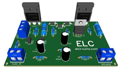
Fig. 1 - PCB  68W Hi-Fi Audio Power Amplifier - IC LM3886T

The LM3886 is a high-performance audio power amplifier capable of delivering 68W of continuous average power to a load and 38W into with 0.1% THD+N from 20Hz–20kHz

The performance of the LM3886, utilizing its Self Peak Instantaneous Temperature (°Ke) (SPiKe) protection circuitry, puts it in a class above discrete and hybrid amplifiers by providing an inherently, dynamically protected Safe Operating Area (SOA)

SPiKe protection means that these parts are completely safeguarded at the output against over-voltage, under-voltage, over-loads, including shorts to the supplies, thermal runaway, and instantaneous temperature peaks. The IC pinout is shown in Figure 2 below.
Fig. 2 - Pinout IC LM3886T

The LM3886 maintains an excellent signal-to-noise ratio of greater than 92dB with a typical low noise floor of 2.0μV. It exhibits extremely low THD+N values of 0.03% at the rated output into the rated load over the audio spectrum, and provides exceptional linearity with an IMD (SMPTE) typical rating of 0.004%.

Features

  • 68W cont. avg. output power into 4Ω at VCC = ±28V
  • 50W cont. avg. output power into 8Ω at VCC = ±35V
  • 38W cont. avg. output power into 8Ω at VCC = ±28V
  • 135W Instantaneous Peak Output Power Capability
  • Signal-to-Noise Ratio ≥ 92dB
  • An Input Mute Function
  • Output Protection from a Short to Ground or to the Supplies via Internal Current Limiting Circuitry
  • Output Over-Voltage Protection against Transients from Inductive Loads
  • Supply Under-Voltage Protection, not Allowing Internal Biasing to Occur when |VEE| + |VCC| ≤ 12V, thus Eliminating Turn-On and Turn-Off Transients
  • 11-Lead TO-220 Package

The Power Supply

The power supply is Symmetrical, for those who will use a 4Ω Loudspeaker, the 2x 20Vac transformer is recommended, because when rectified, it is around 28Vdc.

And for those who will use it at 8Ω, it is recommended the 2x 25Vac transformer, which when rectified, is 35Vdc on average.

The recommended transformer power is about 120W, this means that the transformer current is on average 3.5 Amperes, for mono, if it's stereo, do the duplication, that is, 8 Amperes. 

A good size heat radiator is necessary, since the IC LM3886 works in class AB, there is a great loss in heat at full power, and the recommended filter capacitors is 2 x 10.000uF/50V

The output inductance is formed by 15 turns of enameled wire, with a diameter of approximately 0.5mm, wound around the resistor R8 of 10Ω 1W. The complete schematic diagram is shown in Figure 3 below.
Fig. 3 - Schematic  68W Hi-Fi Audio Power Amplifier - IC LM3886T

Components List

  • U1 ..........................LM3886 Integrated Circuit
  • R1, R3 .................. 2.2K ohms - 1/8W - Resistor  - (red, red, red, gold)
  • R2, R4, R5, R6 ..... 47K ohms - 1/8W - Resistor  - (yellow, violet, orange, gold)
  • R7 ......................... 4R7 ohms - 1W - Resistor  - (yellow, violet, gold, gold)
  • R8 ......................... 10 ohms - 1W - Resistor  - (brown, black, brown, gold)
  • C1 ......................... 2.2uF - 25V - Electrolytic capacitor 
  • C2 ......................... 680pF Polyester capacitor 
  • C3 ......................... 470uF - 50V - Electrolytic capacitor 
  • C4, C8 .................. 100nF - ceramic/polyester capacitor
  • C5, C7 .................. 1000uF - 50V - Electrolytic capacitor
  • C6 ......................... 47pF - ceramic/polyester capacitor
  • C9 ......................... 220nF - ceramic/polyester capacitor
  • C10 ....................... 100uF - 50V - Electrolytic capacitor
  •  L1 ........................ 0.7uH Inductor - *See Text 
  • P1, P2 ................... Block 5mm 2 Pin weldable terminal Connector
  • P3 ......................... Block 5mm 3 Pin weldable terminal Connector
  • Others ................... PCP,  Heat Sink, Wires, Solders and Etc.

We are offering the PCI - Printed Circuit Board, in GERBER, PDF and PNG files, for you who want to do the most optimized assembly, either at home.

If you prefer in a company that develops the board, you can is downloading and make the files in the Download option below.

Files to download, Direct Link:

Click on the link beside: GERBER, PDF and PNG files

If you have any questions, suggestions or corrections, please leave them in the comments and we will answer them soon.

Subscribe to our blog!!! Click here - elcircuits.com!!!

My Best Regards!!!

Monday, May 24, 2021

Arduino: Lesson 1 - What is Arduino?

Fig. 1 - Arduino: Lesson 1 - What is Arduino?


Arduino is an open source electronic prototyping platform or board used for the development of IoT control and automation projects in Digital / Analog Electronics.

Originally started as a research project by Massimo Banzi, David Cuartielles, Tom Igoe, Gianluca Martino and David Mellis at the Ivrea Interaction Design Institute in the early 2000s, it is based on the Processing project, a language for learning to code within the context of the visual arts developed by Casey Reas and Ben Fry, as well as a thesis project by Hernando Barragan on the spinning board. 

Source: Arduino.cc

It consists of a programmable physical circuit board (Microcontroller) and software, or IDE (Integrated Development Environment), used to write and Upload Computer Code to the physical board, and was designed to make Electronics more accessible to Designers, Engineers, Technicians, Enthusiasts and people interested in creating interactive objects or environments.

The first Arduino board was launched in 2005 to help design students, who had no previous experience in electronics or microcontroller programming, to create working prototypes connecting the physical world to the digital world.

Since then, it has become the most popular electronic prototyping tool used by engineers and even large corporations.

An Arduino board can be purchased pre-assembled or, because the hardware design is Open Source, it can be built manually, however, users can adapt the boards according to their needs, as well as update or develop their own versions.

The Arduino platform has become quite popular with people who are starting out with electronics and for a very good reason.

Unlike most previous programmable circuit boards, the Arduino doesn't need separate hardware (called a Programmer, USB Serial Converter, FTDI) to load a new code on the board, you can simply use a USB cable.

In addition, the Arduino IDE uses a simplified version of C ++, making it easy to learn the program. Finally, the Arduino provides a standard form factor that divides the microcontroller functions into a more affordable package.
Fig. 2 - Arduino Uno Board Specification

The Arduino Uno is one of the most popular boards in the Arduino family and a great option for beginners.

Believe it or not, 10 lines of code are all you need to blink the On-board LED on your Arduino

What he does?

Arduino's Hardware and Software was designed for Engineers, technicians, designers, artists, enthusiasts, amateurs, hackers and anyone interested in creating interactive objects or environments.

The Arduino can interact with Buttons, LEDs, Motors, Speakers, GPS Units, Cameras, the Internet and even your Smartphone or TV.

This flexibility combined with the fact that the Arduino software is Open Source, that is, free, the hardware cards are very cheap and both the software and the hardware are easy to learn, leading to a large community of users who contributed code and launched instructions for a huge variety of Arduino-based Projects.

We can use Arduino for just about everything, from robots, heating blanket with temperature limit, machines to count bills, robot arms, etc. The Arduino can be used as the brain behind almost any electronics project.

The Arduino Family

There are different types of Arduino board, each with different capacities. In addition, some of the open source hardware means that others can modify and produce Arduino board derivatives that provide even more form and functionality factors.

If you are not sure which one is right for your project. Here are some options that are suitable for someone new to the Arduino's world:

Arduino Uno (R3)

Arduino Uno is a great option for your first Arduino. It has everything you need to get started and use it for your projects. Here you will find the technical specifications for the Arduino UNO R3:
  • Microcontroller: ATmega328P
  • Digital I/O Pins: 14
  • Analog input pins: 6
  • PWM pins: 6
  • Communication
    • UART
    • I2C
    • SPI
A USB connection, a power connector, a reset button and much more. It contains everything needed to support the microcontroller; Simply connect it to a computer with a USB cable or connect it to a DC power supply or battery to get started.

Sensors

With some simple code, the Arduino can control and interact with a wide variety of sensors - things that can measure light, temperature, degree of flexion, pressure, proximity, acceleration, carbon monoxide, radioactivity, humidity, barometric pressure, voltage, current, among so many others.

Shields

In addition, there are these things called Shields, basically they are pre-assembled circuit boards that fit on top of your Arduino and provide additional features - controlling engines, connecting to the Internet, providing cell phones or other wireless communication, controlling an LCD display and more.

If you have any questions, suggestions or corrections, please leave them in the comments and we will answer them soon.

Subscribe to our blog!!! Click here - elcircuits.com!!!

My Best Regards!!!

Simple 100W Power Amplifier using TIP142 NPN and TIP147 PNP transistors + PCB

Fig 1 - PCB 100W Power Amplifier - TIP142 and TIP147 Transistors

This is a low complexity amplifier, which can be easily assembled by anyone who has basic knowledge in electronics.

This amplifier works with a Class B output stage with a complementary output pair formed by the TIP142 and TIP147 Darlington Transistors.

Operation

The input stage, is formed by a differential pair Q1 and Q2, which are two PNPs A733 transistors, the Q1 transistor receive the input signal for amplification, and Q2 receives the Feedback signal.

Thus assembling a signal loop making with the differential amplifier to control the signal giving stability to the amplifier and avoiding distortion in the circuit.

The second stage consists of a TIP41 transistor, which functions as a Drive, which receives the signal from the differential pair and amplifies it to delivery a sufficient current at the base of the output transistors.
This amplifier has an output power of approximately 100 watts, to get this output power will depend on the Power Supply voltage, with a supply voltage of + 50V / - 50V, with a current of 3A.

In our tests, it was possible to get a little more than 100W. The schematic diagram circuit, is in Figure 2 below, it is a very simple circuit to build, with few external components.

However, be careful, it works with a total voltage of 90V, be careful not to change any component polarity, don't short the amplifier circuit.
Fig 2 - Schematic Simple 100W Power Amplifier with  TIP142 NPN and TIP147 PNP transistors

Power supply

The power supply for this circuit amplifier is symmetrical, in our tests a Transformer with a +36V 0V -36V AC, center-tape was used, with a current 3 Amperes, after the CA voltage goes through the rectification, it will average 50V DC.

Components List

  • Semiconductor 
    • Q1, Q2 .... A733 - PNP transistor 
    • Q3 ........... TIP41C - NPN transistor
    • Q4 ........... TIP142 - NPN power transistor 
    • Q5 ............TIP147 - PNP power transistor 
    • D1, D2 .... 1N4007 - Diode 

  • Resistors 
    • R1, R2 ..... 22K ohms - 1/8W - Resistor  - (red, red, orange, gold)
    • R3 ........... 1K5 ohms - 1/8W - Resistor  - (brown, green, red, gold)
    • R4 ........... 220 ohms - 1/8W - Resistor  - (red, red, brown, gold)
    • R5 ........... 27K ohms - 1/8W - Resistor  - (red, violet, orange, gold)
    • R6 ........... 27 ohms - 1/8W - Resistor  - (red, violet, black, gold)
    • R7, R8 .... 3K3 ohms - 1W - Resistor  - (orange, orange, red, gold)
    • R9, R10 ... 022 ohms - 3W - Resistor  - (red, red, gold, silver)

  • Capacitors
    • C1 .......... 2.2uF - 25V - Electrolytic capacitor 
    • C2 .......... 100uF - 63V - Electrolytic capacitor 
    • C3 .......... 10uF - 63V - Electrolytic capacitor

  • Miscellaneous 
    • P1, P2 ..... Block 5mm 2 Pin weldable terminal Connector
    • P3 ........... Block 5mm 3 Pin weldable terminal Connector
    • Others .... Printed Circuit Board, Wires, Solders, Etc.

We are offering the PCI - Printed Circuit Board, in GERBER, PDF and PNG files, for you who want to do the most optimized assembly, either at home.

If you prefer in a company that develops the board, you can is downloading and make the files in the Download option below.

Files to download, Direct Link:

Click on the link beside: GERBER, PDF and PNG files

If you have any questions, suggestions or corrections, please leave them in the comments and we will answer them soon.

Subscribe to our blog!!! Click here - elcircuits.com!!!

My Best Regards!!!

Friday, May 21, 2021

200W RMS Power Amplifier using 2SC2500 AND 2SA1943 transistors + PCB

Fig. 1 - 200W RMS Power Amplifier using 2SC2500 AND 2SA1943 transistors


This Power Amplifier have a moderate sound quality, and it's a simple circuit to assemble, using 4 complementary output transistors, 2 x NPN 2SC2500 and 2 x PNP 2SA1943

This amplifier is quite common to find and it has a good sound quality, uses specific power transistors for audio, making these amplifiers a good circuit amplifier to building.


This is a power amplifier, posted by our partner fvml.com.br, we are authorized to replicate any post, so we took these posts from them and implemented the volume control and changed the layout a little. This partnership allows us to do this, and they are also free to repost our posts.

The circuit is supplied with a symmetrical power supply and can be supplied with a voltage between 30V to 65V, for greater performance you must use the 60V, with at least current 4 Amperes.

The schematic diagram is shown in Figure 2 below, it is a simple amplifier, and often found on the internet for sale, it has a good quality and complies with the promised power.
Fig. 2 - 200W RMS Power Amplifier with 2SC2500 and 2SA1943

Power supply

The power supply for this circuit amplifier is symmetrical, in our tests a Transformer with a 42V - 0 - 42V center-tape was used, with a 5 Amperes current, you can use a lower current, up to 4 Amps minimum, which will play perfectly.

Nothing prevents you from using a lower voltage, as this amplifier has a tolerance regarding its supply voltage, and can normally play "with loss in output power" with voltages ranging from 24V to 60V without too many problems.

Components List

  • Q1, Q2, Q3 .................. A1015 - PNP transistor 
  • Q5, Q6 ......................... TIP41C - NPN transistor
  • Q4, Q7 ......................... TIP42C- PNP transistor
  • Q8, Q10 ....................... 2SC5200 - NPN power transistor 
  • Q9, Q11 ....................... 2SA1943 - PNP power transistor 
  • D1, D2, D3, D4, D5 .... 1N4007 - Diode 
  • P1 ................................ 47K - Potentiometer 
  • C1 ............................... 2.2uF - 25V - Electrolytic capacitor 
  • C2 ............................... 47uF - 63V - Electrolytic capacitor 
  • C3 ............................... 330pF - Ceramic / polyester capacitor 
  • C4 ............................... 100nF ceramic / polyester capacitor
  • R1 ............................... 10K ohms - 1 / 4W - Resistor  - (brown, black, orange)
  • R2 ............................... 18k ohms - 1 / 4W - Resistor  - (brown, gray, orange)
  • R3 ............................... 820 ohms - 1 / 4W - Resistor  - (gray, red, brown)
  • R4 ............................... 270 ohms - 1W - Resistor  - (red, violet, brown)
  • R5 ............................... 1K ohms - 1 / 4W - Resistor  - (brown, black, red)
  • R6 ............................... 18K ohms - 1 / 4W - Resistor  - (brown, gray, orange)
  • R7 ............................... 330 ohms - 1 / 4W - Resistor  - (orange, orange, brown)
  • R8 ............................... 56 ohms - 1W - Resistor  - (green, blue, black)
  • R9 ............................... 27 ohms - 1W - Resistor  - (red, violet, black)
  • R10, R11 .................... 6R8 ohms - 1W - Resistor - (blue, gray, gold)
  • R12, R13 .................... 100 ohms - 1W - Resistor  - (brown, black, brown)
  • R14, R15, R16, R17 ... 033 ohms - 5W - Resistor  - (orange, orange, gold)
  • R18, R19 .................... 10 ohm resistor - 1W - (brown, black, black)
  • B1, B2 ........................ WJ2EDGVC-5.08-2P Connector
  • B3 ............................... WJ2EDGVC-5.08-3P connector
  • L1 ............................... Coil - 5uH Air Core
  • Others ......................... Printed Circuit Board, Wires, Solders and Etc.

We are offering the PCB - Printed Circuit Board, in GERBER, PDF and PNG files, for you who want to do the most optimized assembly, either at home.

If you prefer in a company that develops the board, you can is downloading and make the files in the Download option below.

Files to download, Direct Link:

Click on the link beside: GERBER, PDF and PNG files

If you have any questions, suggestions or corrections, please leave them in the comments and we will answer them soon.

Subscribe to our blog!!! Click here - elcircuits.com!!!

My Best Regards!!!

Wednesday, May 19, 2021

40W Stereo 14.4V Car Audio Power Amplifier using TDA8560Q IC + PCB

Fig. 1 - PCB 40W Stereo Car Amplifier TDA8560Q

For Portuguese Version, Click Here!

This is a super easy to build Stereo Car Audio Power Amplifier circuit, due to the number of external components being few, it makes this amplifier quite viable for those who want to build a power amplifier and super simple and quick to do.

The TDA8560Q is an integrated Class-B output amplifier in a 13-lead Single-In-Line (SIL) power package.

This Car Audio Amplifier Circuit gives an output power 2×40W / 2 Ω in BTL configuration. The device is primarily developed for car radio applications.  

The TDA8560Q contains two identical amplifiers and can be used for bridge applications. The gain of each amplifier is fixed at 40 dB. Special features of the device are as follows.

You might also be interested in:

Mode select switch (pin 11)

  • Standby: low supply current (<100 µA)
  • Mute: input signal suppressed
  • Operating: normal on condition.

Since this pin has a very low input current (<40 µA), a low cost supply switch can be applied. To avoid switch-on plops, it is advised to keep the amplifier in the mute mode during ≥100 ms (charging of the input capacitors at pin 1 and pin 13).

The schematic diagram of the Car Amplifier Circuit, is in Figure 2 below, it is a very simple circuit to build, with few external components, however, it is a very powerful circuit, which provides 80W in two 2 Ohms Speakers.

Fig. 2 - 40W Stereo 14.4V Car Audio Power Amplifier - IC TDA8560Q

The operating voltage of this circuit can vary between 6V to 18V DC, which opens the possibilities of use in amplifier for; Residential Sound, Car Stereo, Boombox, Computer Speaker, among other types of portable audio amplifiers ... Since it has a common power supply and low power voltage, this circuit amplifier is ideal for these purposes.

Components List

  • U1 ..................TDA8560Q Integrated Circuit
  • R1, R2, R3 .... 10K ohms - 1/8 W Resistor - (brown, black, orange, gold)
  • C1, C2 ........... 470nF Polyester Capacitor
  • C3 .................. 47uF - 35V Electrolytic capacitor 
  • C4 .................. 2200uF - 35V Electrolytic capacitor
  • C5 .................. 100nF Ceramic Capacitor
  • RP1, RP2 ....... 20K ohms Potentiometer 
  • JP1, JP2 .......... Female RCA Connectors to PCB
  • P1, P2, P3 ....... PCB Terminal Blocks
  • Others ............. Wires, Welds, Posts, PCB, Etc.

We are making available the files containing the PCB, the Schematic Diagram, the PDF, GERBER, and JPG, and providing a direct link to download for free in a direct link, "MEGA".

Direct link to download

Click in the link  to download the Files: PCB Layout, PDF, GERBER, JPG

If you have any questions, suggestions or corrections, please leave them in the comments and we will answer them soon.

Subscribe to our blog!!! Click here - elcircuits.com!!!

My Best Regards!!!

Sunday, April 18, 2021

300W RMS Power Amplifier - 2SC3858 and 2SA1494 Transistors + PCB

Fig. 1 - PCB 300W RMS Power Amplifier - 2SC3858 and 2SA1494 Transistors


This is a 300W RMS Power Amplifier using complementary power transistors 2SC3858 and 2SA1494, this circuit amplifier isn't so simple to building, it will be necessary to have at least a little experience in electronics.

To set up this circuit, its complexity is moderate, but, if you haven't skills in electronics circuits, we advise you not to do it, however, if you really want to do it, call someone with experience, to help you.

This amplifier has an excellent audio quality, and use four output power transistors, it reaches a sound power of 300W RMS under load of 4 ohms, powered with a symmetric power supply. You can check the schematic diagram in Figure 2 below.

Fig. 2 - Schematic 300W RMS Power Amplifier - 2SC3858 and 2SA1494 Transistors

Power Supply

The power supply consists of a symmetrical transformer 45V - 0 - 45V center tape, 6 Amperes current supply, can be used. After rectified, we will have approximately 63Vcc at the output of the symmetrical power supply .

Components list

  • Q1, Q2, Q3, Q5 ......... C1815 NPN Transistor
  • Q4 .............................. A1015 PNP Transistor 
  • Q7 .............................. TIP 42C PNP Transistor
  • Q8, Q9 ....................... 2SC3858 NPN Power Transistor
  • Q10, Q11 ................... 2SA1494 PNP Power Transistor
  • Q6 .............................. TIP41C NPN Transistor

  • D1 to D7 .................... 1N4148 diode, or equivalent diode 1N4001 
  • C1, C4 ......................... 2.2uF - 25V Electrolytic Capacitor   
  • C2 ............................... 220pF Polyester / Ceramic Capacitor 
  • C8 ............................... 100nF Polyester / Ceramic Capacitor 

  • R2, R10 ....................... 47k ohms resistor (yellow, violet, orange, gold)
  • R3, R5 ......................... 2.2k ohms resistor (red, red, red, gold)
  • R4 ................................ 270 ohms resistor (red, violet, black, gold)
  • R6, R7 ......................... 51K ohms - 1/2W resistor (green, brown, orange, gold)
  • R8, R9, ........................ 100 ohms resistor (brown, brown, black, gold)
  • R11 .............................. 470 ohms resistor (yellow, violet, brown, gold)
  • R12 .............................. 390 ohms resistor (orange, white, brown, gold)
  • R13, R14 ..................... 100 ohms - 2W resistor (brown, brown, black, gold)
  • R17, R18 ...................... 6R8 ohms - 1W resistor (blue, gray, gold, gold)
  • R15, R16, R19, R20 .... 100 ohms - 1W resistor (brown, brown, black, gold)
  • R21, R22, R23, R24 .... 0.33 ohms - 5W resistor (orange, orange, gold, gold)
  • R25 .............................. 22 ohms resistor (red, red, black gold)
  • R26 .............................. 10 ohms - 1W resistor - (brown, black, black. gold)

  • P1, P2 ....... 2 Pin - PCB Terminal Blocks - EK500V-XXP 20A - or equivalent
  • P3 ............. 3 Pin - PCB Terminal Blocks - EK500V-XXP 20A - or equivalent

  • L1 ............. 5uH - Air Core Coil 10 Turns 18AWG, 3/8" Core

  • Others ...... Loudspeaker, Wires, Solders and Etc.


For those who want to download materials such as the schematic diagram in PDF, PCB Layout,  GERBER and JPG, we are providing a direct link to download all the material.

Direct link to download

Click in the link below to download the Files: PCB Layout, PDF, GERBER, JPG

If you have any questions, suggestions or corrections, please leave them in the comments and we will answer them soon.

Subscribe to our blog!!! Click here - elcircuits.com!!!

My Best Regards!!!