Sunday, September 19, 2021

Arduino: Lesson 5 - Reading Potentiometer and Showing Values On Serial Monitor

Fig. 1 - Arduino Lesson 5 - Reading Potentiometer and Showing Values On Serial Monitor

Welcome to Lesson 5 - Basic Arduino Course

Today we are going to learn how to read a Potentiometer end showing the Values on Serial Monitor.
In this example, we will use a potentiometer, however, this same concept is used for most analog sensors. 

What will differentiate will be the type of calculation used, with reference to each sensor.

We will use the analogRead() function, to read A0 PIN, in Arduino we have 6 Analog Ports, which goes from A0 to A5, so we can make readings from up to 6 sensors simultaneously without having to use external hardware.

Hardware Required

  • Arduino Board
  • A 10K Potentiometer
  • Wires
  • Protoboard (optional)

The Circuit

The potentiometer works like a voltage divider. When you turn the shaft of the potentiometer, you change the resistance on either side of the center pin (or wiper) of the potentiometer. 

This changes the relative resistances between the center pin and the two outer pins, so you get a different voltage at the analog input. 

When the shaft is fully rotated in one direction, there is no resistance between the center pin and the pin connected to ground.
The middle pin varies from 0Kohms to 10Kohms, which is the value of the potentiometer we will use.

This resistance is sensed by the voltages at the ends of the potentiometer, causing the center pin to vary between 0V and 5V

And the voltage variation that comes from the Center Pin of the potentiometer goes to the A0 Analog Port.

In Figure 2, you can see the schematic of the potentiometer and the Arduino. We use a breadboard to make the connections easier, but you can also connect the wires directly from the A0 terminal in the middle of the potentiometer, connecting the outer pin to 5V positive and the outer pin to the negative GND of the Arduino.

Fig. 2 - Reading Potentiometer and Showing Values On Serial Monitor - tinkercad.com

The Code

The analogRead() function converts the input voltage range, 0 to 5 volts, to a digital value between 0 and 1023. This is done by a circuit within the microcontroller called analog-to-digital converter, or ADC.

Then, if the voltage at the center pin is 0 volts, analogRead() returns 0. When the shaft is turned all the way the other way, there is no resistance between the middle pin and the pin connected to 5 volts

If the voltage on the middle pin is then 5 voltsanalogRead() returns 1023. In between, analogRead() returns a number between 0 and 1023 that is proportional to the voltage applied to the pin.

After building the circuit, connect your Arduino board to your computer, launch Arduino Software (IDE), copy the code below and paste it into your Arduino IDE. But first let us understand the code line by line. 

  • In Line 3, we declared variable sensorPin which is set to Analog Pin A0 where we receive the value of the connected potentiometer. 
  • In Line 4, we create a variable senorPin that stores the value of the sensor that we also use for the potentiometer.

01
02
03
04
05
// Arduino: Lesson 5 -  Reading Potentiometer and Showing Values On Serial Monitor

int sensorPin = A0           // Read the Analogic Pin A0 Values  into a variable
int sensorValue = 0;          // Variable to store the value coming from the sensor "Potentiometer"

  • In Line 6, we enter the void setup() function. This function is read only once when the Arduino is started.

  • In Line 7, we begin serial communication by declaring the Serial.begin() function. At 9600 bits of data per second, this is the speed at which your computer will communicate with your Arduino Serial.
01
...
06
07
08
09
// Arduino: Lesson 5 -  Reading Potentiometer and Showing Values On Serial Monitor

void setup() {                      // This function is called once when the program starts
Serial.begin(9600);  // Begin the Serial Monitor with bounce rate in 115200
}

  • After setting the initializations, in Line 10 we will enter the void loop() function.

  • In Line 11, we use the variable sensorValue to store the resistance value, which is between 0 and 10K (read by the Arduino as a value between 0 and 1023) and controlled by the potentiometer.

  • In Line 13, we use the command Serial.println(), it is print out the value controlled by the potentiometer, this value will read with value between 0 and 1023 in your Serial Monitor.

  • In Line 14, we run the delay() function, for greater system stability.

1
...
10
11
12
13
14
15
16
17
// Arduino: Lesson 5 -  Reading Potentiometer and Showing Values On Serial Monitor

void loop() { // The loop function runs over and over again forever
sensorValue = analogRead (sensorPin);      // Read the input on analog pin A0

 Serial.println(sensorValue);                       // Print out the value you read
   delay(1);                                                   // delay in between reads for stability
}

//------------------------------------- www.elcircuits.com --------------------------------------------
Now you can copy the code and upload it to your Arduino. After that, if you open your Serial Monitor in Arduino Software (IDE) (by clicking on the icon that looks like a lens on the right side of the green top bar or using the keyboard shortcut Ctrl+Shift+M), you should see a steady stream of numbers in the range 0-1023 that correlate with the position of the pot. When you turn your potentiometer, these numbers respond almost instantly.

The complete code is showed in the sketch below!

1
2
3
4
5
6
7
8
9
10
11
12
13
14
15
16
// Arduino: Lesson 5 -  Reading Potentiometer and Showing Values On Serial Monitor

int sensorPin = A0       // Read the Analogic Pin A0 Values  into a variable
int sensorValue = 0;       // Variable to store the value coming from the sensor "Potentiometer"

void setup() {                     // This function is called once when the program starts
Serial.begin(9600); // Start serial connection
}
 
void loop() { // The loop function runs over and over again forever
sensorValue = analogRead (sensorPin);      // Read the input on analog pin A0
 
   Serial.println(sensorValue);                     // Print out the value you read
   delay(1);                                                   // delay in between reads for stability
}
//------------------------------------- www.elcircuits.com --------------------------------------------

Next Lesson

Previous Lesson

If you have any questions, suggestions or corrections, please leave them in the comments and we will answer them soon.

Subscribe to our blog!!! Click here - elcircuits.com!!!

My Best Regards!!!

Tuesday, September 7, 2021

Simple 12V battery charger with automatic charging indicator + PCB

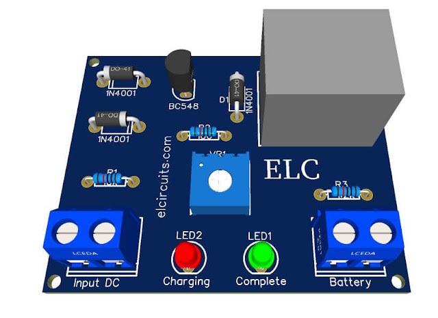
PCB - Simple 12V battery charger with automatic charging indicator

Para versão em Português, click aqui!

This is a Smart Battery Charger, with fully automatic 12V battery charge indicator. It is an extremely simple charger that anyone with little experience can assemble.

The input voltage depends on the power supply you are using, 110Vac or 220Vac. The charging time depends on the power supply you are using and the type of battery you are charging.

To calculate the closest charging time, we can do a simple and objective quick calculation that does not take into account the variations of the resistance factors of the battery, the variations of the charger, the chemical depreciation factor of the battery and so on.

You may be interested in: 

The calculation is quite simple. Let us take an example: you have a UPS 12 volt battery with 7 amps, your power supply is 3 amps

So we know that the battery charge is "more or less" 7 Amps Hour, which means that to fully charge the battery, 7 constant amps are required. Since the power supply is 3 amps, we need to divide 7 amps by 3 amps of power supply.

To charge a battery without damaging it usually requires a current of 10% and a maximum of 20% of its current. For example:

If our battery is 7 amps, the most we need is a 1.4 amp charger, and normal charging consumption is 700 milliamps. This 10% is normally used in devices that are directly connected to the power, such as alarm systems, backup devices and others.

Let's do the calculations using the formula

  • B = battery
  • PS = power supply
  • C = current

C = B / PS

C = 7/3 C = 2.33

Meaning:

Charge "C" lasts 2:33 hours

Two hours and thirty-three minutes to charge

If your PS is different, no problem, look at its supply current and put in the formula to see the approximate result.

Figure 2 shows the complete electrical schematic of the small circuit.

Fig. 2 - Electronic Schematic Simple 12V Automatic Battery Charger

It is important that the power supply delivers 20% more than the battery voltage, e.g. if your battery is 12 V, the power supply must be 14,4 V. You can vary a little, e.g. 13.2 V, "which is 10% of the battery voltage", but you cannot use a 12 V power supply to charge a 12 V battery as there will be no potential difference.

Here is how to use the charger:

When all the assembly is done, carefully check for wrong parts, reverse polarity diodes and shorts in the terminals after checking everything.

Connect the positive terminal of the power supply to the input of the +Vcc circuit and the negative terminal of the power supply to the ground circuit of the charger. 

With the potentiometer or trimpot you can regulate the output voltage of the charger, for example you have a 12V battery, normally 12V batteries UPS are charged at 13.2V at 14.4 volts.

Then use a multimeter on the DC volt scale, "it depends on the multimeter", on the output of the charger and set the voltage to the most desired, ie the maximum voltage for it to fire and the green LED will light up.

You can now use your new charger, insert the battery and let it charge until the charger reaches the voltage you set, "limit voltage", it will trigger the relay and turn on the green LED, indicating that the battery has been charged.

A good tip: If you have a spare 12v buzzer, or if you really want to add an audible indicator to your circuit, you can connect these buzzers, which you can easily find in electronics stores and are cheap, to the output where the green LED is lit, which is the full charge indicator, and you can turn on the positive buzzer on the relay output and the negative buzzer directly on the output.

Material List:

  • Q1..................... General purpose NPN transistor, C1815, BC548 etc.
  • D1, D2, D3 ...... Diodes 1N4001.
  • R1 ..................... Resistor 1/8W 10K (Brown, Black, Orange)
  • R2 ..................... Resistor 1/8W 100 Ohms (Brown, Black, Brown)
  • R3 ..................... Resistor 1/8W 1K2 (Brown, Red, Red)
  • VR1 ................. 10K Trimmpot or Potentiometer
  • P1, P2 ............... KF301 2 Pin 5.08mm Pitch Plug-in Screw Terminal Block Connector 
  • RL1 ................... Relay 12V 10A, 5 pins
  • LED1, LED2 .... 3mm LEDs, one Red and one Green
  • Others ............... Printed circuit board, soldering iron, tin, wire, etc.
We offer for download the necessary materials for those who want to assemble with PCI - Printed Circuit Board, the files in PNG, PDF and GERBER files for those who want to send for printing.

Download:


If you have any questions, suggestions or corrections, please leave them in the comments and we will answer them soon.

Subscribe to our blog!!! Click here - elcircuits.com!!!

My Best Regards!!!
Monday, September 6, 2021

1W Amplifier for Stereo Headphone using TDA2822 IC + PCB

Fig. 3 - PCB - 1W Amplifier for Stereo Headphone with IC TDA2822M

Simple headphone amplifier with few external components that is easy and inexpensive to assemble. This IC is designed for amplifying portable devices such as CD players, portable radios, small speakers, etc.

First of all, we will use it to amplify the audio signal for headphones, that is, we will build a headphone amplifier, whether to listen to music from a mobile phone, connect instruments to study, such as electric guitar, bass guitar, ukulele, guitar, or any other audio signal that needs to be amplified. 

You might also be interested in:

The main component is the TDA2822, a monolithic integrated circuit in an 8-pin lead  Mini-dip package. It is intended for use as a dual audio power amplifier in portable audios.

FEATURES

  • Dual Low-voltage power amplifier 
  • Supply voltage down to 1.8V 
  • Low crossover distortion                                
  • Low quiescent current z Bridge or stereo configuration
The maximum input voltage of this IC is 15V DC, so do not apply more than 15V to the IC. The circuit volume can be adjusted using a 47K doble potentiometer is used in the circuit.

The schematic diagram circuit of the 1W audio Amplifier for Stereo Headphone with IC TDA2822M  is shown in Figure 2 below.

Fig. 2 - 1W Amplifier for Stereo Headphone with IC TDA2822M

Material List

  • IC1 .................. Integrated Circuits TDA2822M
  • R1, R2 ............ 1/4W / 4.7Ω Resistor 
  • C1, C2 ............ 1uF - 25V Electrolytic capacitor 
  • C3, C4, C5 ..... 100uF - 25V Electrolytic Capacitor 
  • C6, C7 ............ 0.1uF Polyester capacitor
  • J1, J2 .............. 3.5mm Audio Female Jack Connector 
  • VR1 ................ 47KΩ  Double Potentiometer
  • P1 ................... Connector 2 screw terminal 5mm 2 Pins
  • Others ............ Wires, Solders, pcb, etc.

We offer for download the necessary materials for those who want to assemble with PCI - Printed Circuit Board, the files in PNG, PDF and GERBER files for those who want to send for printing.

Download:


If you have any questions, suggestions or corrections, please leave them in the comments and we will answer them soon.

Subscribe to our blog!!! Click here - elcircuits.com!!!

My Best Regards!!!

Saturday, September 4, 2021

Arduino: Lesson 4 - Read Pushbutton with digitalRead() function

Fig. 1 - Arduino Lesson 4 - Read Pushbutton with digitalRead() function

Welcome to Lesson 4 - Basic Arduino Course

Today we are going to learn how to read a Pushbutton, which when pressed, the Arduino will read and light an LED indicating that the button was pressed. We will use the digitalRead() function.

Hardware Required

  • Arduino Board
  • A Pushbutton
  • LED - optional "You can use the onboard LED"
  • 220 ohm resistor - optional "You can use the onboard resistor"

The Circuit

You can use as an example the built-in LED that most Arduino boards have. This LED is connected to a digital pin 13, however, this number may vary from board type to board type. 

This constant is LED_BUILTIN and allows you to control the built-in LED easily, and the correspondence of this constant is digital pin 13.

However, you can light an external LED with this sketch, you just need to build the same circuit as the previous lesson, Lesson 3, as we will be using the same circuit, only added from the Microswitch as shown in Figure 2 below,

Fig. 2 - Arduino Read a Microswitch with digitalRead  function - tinkercad.com

The Code

After building the circuit, connect your Arduino board to your computer, launch the Arduino Software (IDE), copy the code below and paste it into your Arduino IDE. But first, let's understand the code line by line. 

  • First we have the integer declarations, in Line 4 and in Line 5, they are integer constants, as they will not change their parameters, these are the pins that will connect the Push Button and the LED.

  • In Line 8, we create a variable that will receive the initial value "0", it will receive the state of the switch depending on whether you press it or not, it will change its value.
1
2
3
4
5
6
7
8
9
// Arduino: Lesson 4 - Read Pushbutton with digitalRead() function

  // Constants don't change.   // That's why they are used to set the pin numbers
const int buttonPin = 12;    // The number of the pushbutton pin
const int ledPin =  6;          // The number of the LED pin

// This variable will change according to the state of the LED
int buttonState = 0;            // Variable for reading the pushbutton status

  • After the declarations, we enter the in void setup() function, this function will only be read once at Arduino startup.
    Here where we declare for Arduino where we connect our peripherals. 

  • In Line 11 we use the ledPin declaration as output

  • In Line 12 we declare our buttonPin as input Pullup, its means that we are using the Arduino's internal Pullup resistor, so we don't need to use an external resistor together with the switch.
1
...
10
11
12
13
14
// Arduino: Lesson 4 - Read Pushbutton with digitalRead() function

void setup() {
pinMode(ledPin, OUTPUT); // Initialize digital pin 6 as an output.
   pinMode(buttonPin, INPUT_PULLUP);  // Initialize the pushbutton pin as an input pull up
}

  • After setting the initializations, in Line 15 we will enter the void loop() function.

  • In Line 16we get the state of the switch, when pressed, the variable gets "0", and when released, the variable gets "1".

    You may be thinking, but it shouldn't be the other way around, when you press it it goes to "1" and when I release it it goes to "0".

    Well, remember we use the Arduino's internal Pullup resistor, its means when the switch is released the Pullup resistor leaves the Arduino's gate at HIGH, "1", and when you press the switch it throws the output to the ground, which means we ground output "0" so it goes to LOW.
     
  • In Line 18, we declare a control structure, using the IF conditional, with it we are going to check if the key was pressed, if so, the variable buttonState will receive the value LOW, "0". If released, it will receive the HIGH value "1".
  • In Line 19, the digitalWrite function, command activates ledPin to HIGH level, it means that it goes from 0V to 5V, which makes the LED receive the voltage and lit up. 

  • In Line 20, we have the "else" control structure, that will be triggered if the "if" structure control isn't true.

  • In Line 21, the digitalWrite function, command activates ledPin to LOW level, it means that it goes from 5V to 0V, which makes the LED turn off.
1
...
15
16
17
18
19
20
21
22
23
// Arduino: Lesson 4 - Read Pushbutton with digitalRead() function

void loop() { // The loop function runs over and over again forever
  buttonState = digitalRead(buttonPin);   // Read the state of the pushbutton value

  if (buttonState == LOW) {  // Check if pushbutton is pressed. Case is, the buttonState is LOW
    digitalWrite(ledPin, HIGH); // Turn LED Turn On
  } else {
    digitalWrite(ledPin, LOW);  // Turn LED Turn Off
  }
}

The complete code is showed in the sketch below!

1
2
3
4
5
6
7
8
9
10
11
12
13
14
15
16
17
18
19
20
21
22
23
24
// Arduino: Lesson 4 - Read Pushbutton with digitalRead() function

// Constants don't change.    // That's why they are used to set the pin numbers
const int buttonPin = 12;    // The number of the pushbutton pin
const int ledPin =  6;          // The number of the LED pin

// This variable will change according to the state of the LED
int buttonState = 0;            // Variable for reading the pushbutton status

void setup() {                                // This function is called once when the program starts
pinMode(ledPin, OUTPUT); // Initialize digital pin 6 as an output.
   pinMode(buttonPin, INPUT_PULLUP);   // Initialize the pushbutton pin as an input pull up
}

void loop() {                                      // The loop function runs over and over again forever
  buttonState = digitalRead(buttonPin);   // Read the state of the pushbutton value

  if (buttonState == HIGH) {                     // Check if pushbutton is pressed. Case is, the buttonState is HIGH
    digitalWrite(ledPin, HIGH);                 // Turn LED Turn On
  } else {
    digitalWrite(ledPin, LOW);                  // Turn LED Turn Off
  }
}
//------------------------------------- www.elcircuits.com --------------------------------------------

Next Lesson

Previous Lesson

If you have any questions, suggestions or corrections, please leave them in the comments and we will answer them soon.

Subscribe to our blog!!! Click here - elcircuits.com!!!

My Best Regards!!!