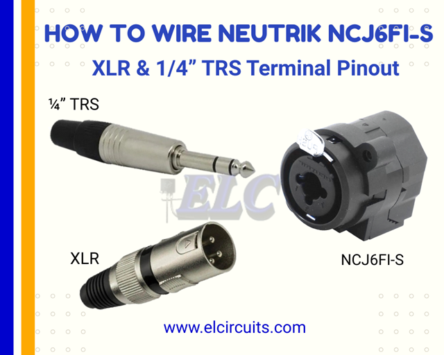
🌐 Idioma / Language: English English Português Português Español Español

Monday, September 20, 2021

How to Wire the Neutrik NCJ6FI-S Combo Connector (XLR / 1/4 inch TRS Wiring Diagram)

Schematic Wiring of Combined Female XLR / 1/4" Neutrik NCJ6FI-S - elcircuits.com
Schematic Wiring of Combined Female XLR / 1/4" Neutrik NCJ6FI-S

🌐 You can read this article in: Português | Español

Hello, electronics enthusiasts!

Today we're going to dive deep into the world of professional audio connectors with a definitive guide on the Neutrik NCJ6FI-S Combined Female XLR/1/4" Plug. If you work with sound systems, build equipment, or are simply an audio enthusiast, this article will solve all your doubts about this essential component.

First of all, I need to clarify a crucial point that many professionals still have doubts about: this NCJ6FI-S combined connector is specially designed for "snake" type audio panels - those you see on the sides of mixing consoles or in professional racks, with multiple inputs strategically organized.

🔍 Why the NCJ6FI-S is Gold for Audio Panels (Snakes)?

The snake (or breakout box) is a fundamental component in any professional audio system, serving as a central hub for connections between microphones, instruments, and the mixing console. The Neutrik NCJ6FI-S connector has become the gold standard for these applications for three main reasons:

  1. Space saving - In an audio panel where every centimeter counts, having a single connector that accepts both XLR and 1/4" is revolutionary
  2. Operational flexibility - Allows the sound technician to connect any type of source without needing adapters
  3. Signal integrity - Designed to maintain the quality of balanced audio even with mixed connections.

🔌 Pin Layout in the Neutrik Female Plug: Understanding the Connector's DNA

Let's unravel together the internal architecture of this little giant. There are 4 main models in Neutrik's line of combined connectors, but what interests us today, and the most used in professional audio panels, is the NCJ6FI-S with its 7 contact pins intelligently distributed.

Pinout of XLR/1/4" Neutrik Connector - elcircuits.com
Fig. 2 - Pinout of XLR/1/4" Neutrik Connector

What makes this connector so special is how it manages two different connection protocols in a single body: the 3-pin XLR (for balanced signals) and the 3-section 1/4" TRS (for stereo or balanced mono). It's like having two connectors in one, without losing quality!

Schematic Diagram of Neutrik NCJ6FI-S Neutrik - elcircuits.com
Fig. 3 - Schematic Diagram of Neutrik NCJ6FI-S Neutrik

Practical analogy: Think of the NCJ6FI-S as an "audio international airport". Just as an airport receives flights from different airlines in connected terminals, this connector receives signals from different formats (XLR and 1/4") in a single "terminal", allowing them to share the same infrastructure without interference.

"TRS" - When You Need Direct Instrument Connection

Let's start with the most common scenario in studios and stages: direct connection of instruments like guitars, basses, and keyboards. When you're using only the 1/4" TRS connector, the connections follow a specific pattern that ensures signal integrity.

The secret lies in the three contact points of the 1/4":

  • T (Tip) - The positive signal or left channel
  • R (Ring) - The negative signal or right channel
  • S (Sleeve) - The ground

In the diagram below (Figure 4), you'll see exactly how to make the connection when using only the 1/4" connector in your audio snake or audio panel project.

Schematic wiring of Neutrik NCJ6FI-S connector for TRS input connector - elcircuits.com
Fig. 4 - Schematic wiring of Neutrik NCJ6FI-S connector for TRS input connector

Pro tip for designers: When building your snake for instruments, use cables with double shielding for TRS connections. The NCJ6FI-S has excellent noise rejection, but good cable shielding perfectly complements its characteristics, eliminating that annoying hum during recordings!

"XLR" - For Microphones and Professional Balanced Signals

Now, when you're working with microphones or any other signal that needs a balanced connection, the XLR side of the connector comes into play. The XLR standard is the heart of professional audio systems, and understanding its pinout is fundamental.

On the XLR connector:

  • Pin 1 - Ground (Shield/Ground)
  • Pin 2 - Positive signal (Hot)
  • Pin 3 - Negative signal (Cold)

This pinout pattern is crucial for noise rejection over long distances - an essential feature in any professional audio panel. The diagram below (Figure 5) shows exactly how to make the connection when using only the XLR connector in your project.

Schematic Wiring of Neutrik NCJ6FI-S for XLR Input Connector - elcircuits.com
Fig. 5 - Schematic Wiring of Neutrik NCJ6FI-S for XLR Input Connector

Here's a detail that many experienced technicians still get confused about: the XLR standard for microphones is different from the XLR standard for speakers. In the case of the NCJ6FI-S, we're specifically talking about the standard for microphones (3-pin XLR), where pin 2 is "hot" and pin 3 is "cold".

🔍 Did You Know?

The current XLR pinout standard (Pin 2 = Hot) was established by the AES (Audio Engineering Society) in the AES14-1992 standard. Before that, some manufacturers used the inverted standard (Pin 3 = Hot), which caused a lot of confusion. Fortunately, today we have a universal standard thanks to this standard!

⚡ Combined Connection: The Real Power of the NCJ6FI-S in Audio Panels

Now we come to the heart of our article: how to configure the connector to work with both types of connection simultaneously - which makes it the perfect component for snakes and professional audio panels.

The magic happens through a simple connection between the corresponding pins, creating a circuit that allows the signal to flow correctly regardless of the type of connector you're using. It's like having an "automatic switch" inside the connector!

Schematic wiring of Neutrik NCJ6FI-S for combined XLR/TRS connector - elcircuits.com
Fig. 6 - Schematic wiring of Neutrik NCJ6FI-S for combined XLR/TRS connector

The combined connection follows these simple but fundamental rules:

  • XLR Pin 1 connected to TRS Pin S (Ground)
  • XLR Pin 2 connected to TRS Pin T (Positive signal)
  • XLR Pin 3 connected to TRS Pin R (Negative signal)

This intelligent configuration is what allows you to connect an XLR microphone to a connector that also accepts 1/4", without needing manual switches or additional configurations. It's pure audio engineering in action!

"Mono" - Configuration for 1/4" TS (Mono) Connector

For applications that require only mono signal (like most musical instruments), you can simplify the connection using only two of the three contacts of the 1/4". This is the classic "TS" (Tip-Sleeve) configuration that you find in guitars and basses.

Wiring diagram of Neutrik NCJ6FI-S connector and TS - 1/4" connector - elcircuits.com
Fig. 7 - Wiring diagram of Neutrik NCJ6FI-S connector and TS - 1/4" connector

In this configuration:

  • T (Tip) - Audio signal
  • S (Sleeve) - Ground
  • R (Ring) - Not connected (or connected to ground for better noise rejection)
Attention, guitarists! Many guitarists don't know, but connecting the ring to ground in the mono configuration can significantly improve noise rejection, especially in environments with a lot of electromagnetic interference. It's a small adjustment that makes a big difference in your sound!

⚙️ Technical Features That Make the NCJ6FI-S a Gold Standard in Professional Audio

Now that you already understand the logic behind the connections, let's dive into the technical specifications that make the Neutrik NCJ6FI-S the most reliable combined connector on the market. Don't worry - I'll explain each feature in a practical way, relating it to its real use in the day-to-day of professional audio.

🔧 Ultra-Low Contact Resistance: The Secret to Clean Signal

With contact resistance below 10 mΩ on the XLR and 20 mΩ on the 1/4", the NCJ6FI-S ensures that practically no signal is lost in the connection. This means that subtle detail in the vocalist's voice or the rich harmonic of the guitar arrives intact at the mixing console - without loss of quality or introduction of noise.

Practical tip: In large PA systems, where signals travel long distances, this low resistance is critical to avoid signal degradation. It's like having a perfectly smooth road for your audio signal to travel!

🛡️ Industrial Durability: Designed to Survive the Most Intense Shows

When you're working at professional events, you can't risk a connector failing in the middle of the show. The NCJ6FI-S was designed to withstand more than 1,000 connection/disconnection cycles without loss of quality - which means you can assemble and disassemble your system hundreds of times without worrying.

⚡ Specifications That Really Matter for Your Snake Project

Let's translate those technical tables provided by the manufacturer into clear and real parameters for your project. It's not enough to know the numbers - you need to understand how they impact your daily work:

🔌 Rated Current: 7.5A (XLR and 1/4")

This specification means that the connector can handle high-power signals without overheating or degrading. For context: a typical microphone signal operates around 0.001A. This gives an impressive safety margin of 7,500 times above what's needed!

⚠️ Beware of imitations: Generic connectors often have rated current below 1A, which can cause signal loss or even damage in high-power systems.

📏 Panel Thickness: Maximum 7mm

This specification is crucial when you're designing your snake or audio panel. The NCJ6FI-S was designed to fit perfectly in standard panels from 1.5mm to 7mm thick - the most common range in professional racks.

Pro tip for manufacturing: When designing your mounting board, leave a 0.5mm clearance around the connector to facilitate installation and avoid mechanical stresses.

🌡️ Temperature Range: -30°C to +80°C

This is one of the features that makes the NCJ6FI-S ideal for professional use in any weather condition. Whether in an air-conditioned studio or at an outdoor festival in the summer, the connector maintains its performance.

"I've used these connectors in shows in Alaska (-20°C) and in the Arizona desert (+45°C) without any performance problems." - Testimony from a professional sound technician

🔗 Related Projects That May Be of Interest

Frequently Asked Questions About: Neutrik NCJ6FI-S (XLR/1/4") Connector - FAQ

1. What is the Neutrik NCJ6FI-S connector?

It's a combined receptacle that unites in a single body the female XLR and 1/4" (TRS/TS) connectors, allowing greater versatility in mixing consoles, audio equipment, and musical instruments.

2. What's the difference between XLR and 1/4" connections on the NCJ6FI-S?

  • XLR (Canon): Used mainly for microphones and balanced signals.
  • 1/4" TRS: Used for stereo or balanced connections.
  • 1/4" TS: Used in mono signals, like guitars and basses.

3. How many pins does the connector have and how are they distributed?

The NCJ6FI-S model has 7 contact pins, being:

  • 4 pins dedicated to the XLR input.

  • 3 pins dedicated to the TRS/TS (1/4") connector.

4. Is it possible to use the XLR and TRS inputs at the same time?

Yes. The combined connector allows parallel connection of XLR and TRS, just make the jumps between the corresponding pins (1 with S, 2 with T, 3 with R), as shown in the manufacturer's schematic diagram.

5. What are the main electrical characteristics of the NCJ6FI-S?

  • Contact resistance: < 10 mΩ (XLR), < 20 mΩ (1/4").
  • Rated current: up to 7.5 A per contact.
  • Rated voltage: up to 50 V.
  • Insulation resistance: > 10 GΩ.
  • Dielectric withstand: 1.5 kVdc.

6. What are the advantages of using the NCJ6FI-S in audio projects?

The main advantages are:

  • Space saving: A single connector replaces two.
  • Versatility: Accepts XLR, TRS and TS.
  • Durability: More than 1000 insertion/removal cycles.
  • Robust construction: Made with high-quality materials from Neutrik.

7. What's the difference between the NCJ6FI-S and the NCJ6FI-M?

Detailed comparison: This is a question that causes a lot of confusion! Both are combined XLR/1/4" connectors from Neutrik, but they have different applications:

Feature NCJ6FI-S NCJ6FI-M
Mounting Type Panel mounting (front) PCB mounting (circuit board)
Main Application Audio panels (snakes) Internal electronic equipment
Fastening Front screws Board soldering
Mechanical Resistance High (for external use) Moderate (for internal use)

✅ Teacher's tip: For snakes and professional audio panels, always choose the NCJ6FI-S. The "S" means "Socket" (socket for panel), while the "M" means "Module" (module for PCB).

💡 Professional Tips to Maximize Your NCJ6FI-S

After years of working with these connectors, I want to share some tips I've learned in practice - those that aren't in the manual, but make all the difference:

🔧 Perfect Soldering Technique for Impeccable Connections

Most problems with connectors come from inadequate soldering. Follow this professional process:

  1. Prepare the wires: Strip 5mm of insulation and "twist" the strands
  2. Pre-heat the pin: Apply solder to the tip of the iron, then touch the pin for 2 seconds
  3. Quick soldering: Touch the wire to the heated pin and apply solder - it should take less than 3 seconds
  4. Visual inspection: The solder should form a smooth cone, not a ball

"A well-soldered connector should look like a perfect drop of water - not too little, not too much. It's the key to noise-free connections!" - Mixing console maintenance technician.

"Excellence in audio is in the details that most ignore. A quality connector is not a cost - it's an investment in the clarity of your sound." - Prof. Audio.

🚀 Conclusion: Transforming Knowledge into Audio Excellence

We've reached the end of this definitive guide on the Neutrik NCJ6FI-S, but in reality, it's just the beginning of your journey to master the art of professional audio panels. Remember that the quality of your system starts with the quality of the connections - and now you have all the necessary knowledge to create impeccable snakes.

💡 Summary of Key Points You Can't Forget

  • The NCJ6FI-S is Gold for snakes: Saves space, offers flexibility and maintains signal integrity
  • Combined connection is simple: Just connect XLR Pin 1 to TRS S, Pin 2 to T, and Pin 3 to R
  • Authenticity is crucial: Counterfeit connectors are the cause of 70% of noise problems in audio systems
  • Perfect soldering makes a difference: Maximum contact time of 3 seconds and quality solder are non-negotiable
  • Planning is everything: Always leave 10-20% of extra connectors for future expansion

"A quality connector is not a cost - it's an investment in the clarity of your sound." - Prof. Audio

Now that you master all the secrets of the NCJ6FI-S, you're prepared to elevate your audio projects to a new professional level. It doesn't matter if you're an experienced technician, a beginner designer, or an audio enthusiast - this knowledge will make all the difference in the quality of your work.

Original article published on FVML (Portuguese) – july 7, 2019

👋 I hope you enjoyed it!!!

If you have any questions, suggestions, or corrections, feel free to share them in the comments — we’ll be glad to help and improve this guide together!

👉 Stay updated with our latest electronic projects, tutorials, and DIY guides. Subscribe to ElCircuits and never miss a new post!

Best regards,
The ElCircuits Team ⚡

Sunday, September 19, 2021

Arduino: Lesson 5 - Reading Potentiometer and Showing Values On Serial Monitor

Fig. 1 - Arduino Lesson 5 - Reading Potentiometer and Showing Values On Serial Monitor

Welcome to Lesson 5 - Basic Arduino Course

Today we are going to learn how to read a Potentiometer end showing the Values on Serial Monitor.
In this example, we will use a potentiometer, however, this same concept is used for most analog sensors. 

What will differentiate will be the type of calculation used, with reference to each sensor.

We will use the analogRead() function, to read A0 PIN, in Arduino we have 6 Analog Ports, which goes from A0 to A5, so we can make readings from up to 6 sensors simultaneously without having to use external hardware.

Hardware Required

  • Arduino Board
  • A 10K Potentiometer
  • Wires
  • Protoboard (optional)

The Circuit

The potentiometer works like a voltage divider. When you turn the shaft of the potentiometer, you change the resistance on either side of the center pin (or wiper) of the potentiometer. 

This changes the relative resistances between the center pin and the two outer pins, so you get a different voltage at the analog input. 

When the shaft is fully rotated in one direction, there is no resistance between the center pin and the pin connected to ground.
The middle pin varies from 0Kohms to 10Kohms, which is the value of the potentiometer we will use.

This resistance is sensed by the voltages at the ends of the potentiometer, causing the center pin to vary between 0V and 5V

And the voltage variation that comes from the Center Pin of the potentiometer goes to the A0 Analog Port.

In Figure 2, you can see the schematic of the potentiometer and the Arduino. We use a breadboard to make the connections easier, but you can also connect the wires directly from the A0 terminal in the middle of the potentiometer, connecting the outer pin to 5V positive and the outer pin to the negative GND of the Arduino.

Fig. 2 - Reading Potentiometer and Showing Values On Serial Monitor - tinkercad.com

The Code

The analogRead() function converts the input voltage range, 0 to 5 volts, to a digital value between 0 and 1023. This is done by a circuit within the microcontroller called analog-to-digital converter, or ADC.

Then, if the voltage at the center pin is 0 volts, analogRead() returns 0. When the shaft is turned all the way the other way, there is no resistance between the middle pin and the pin connected to 5 volts

If the voltage on the middle pin is then 5 voltsanalogRead() returns 1023. In between, analogRead() returns a number between 0 and 1023 that is proportional to the voltage applied to the pin.

After building the circuit, connect your Arduino board to your computer, launch Arduino Software (IDE), copy the code below and paste it into your Arduino IDE. But first let us understand the code line by line. 

  • In Line 3, we declared variable sensorPin which is set to Analog Pin A0 where we receive the value of the connected potentiometer. 
  • In Line 4, we create a variable senorPin that stores the value of the sensor that we also use for the potentiometer.

01
02
03
04
05
// Arduino: Lesson 5 -  Reading Potentiometer and Showing Values On Serial Monitor

int sensorPin = A0           // Read the Analogic Pin A0 Values  into a variable
int sensorValue = 0;          // Variable to store the value coming from the sensor "Potentiometer"

  • In Line 6, we enter the void setup() function. This function is read only once when the Arduino is started.

  • In Line 7, we begin serial communication by declaring the Serial.begin() function. At 9600 bits of data per second, this is the speed at which your computer will communicate with your Arduino Serial.
01
...
06
07
08
09
// Arduino: Lesson 5 -  Reading Potentiometer and Showing Values On Serial Monitor

void setup() {                      // This function is called once when the program starts
Serial.begin(9600);  // Begin the Serial Monitor with bounce rate in 115200
}

  • After setting the initializations, in Line 10 we will enter the void loop() function.

  • In Line 11, we use the variable sensorValue to store the resistance value, which is between 0 and 10K (read by the Arduino as a value between 0 and 1023) and controlled by the potentiometer.

  • In Line 13, we use the command Serial.println(), it is print out the value controlled by the potentiometer, this value will read with value between 0 and 1023 in your Serial Monitor.

  • In Line 14, we run the delay() function, for greater system stability.

1
...
10
11
12
13
14
15
16
17
// Arduino: Lesson 5 -  Reading Potentiometer and Showing Values On Serial Monitor

void loop() { // The loop function runs over and over again forever
sensorValue = analogRead (sensorPin);      // Read the input on analog pin A0

 Serial.println(sensorValue);                       // Print out the value you read
   delay(1);                                                   // delay in between reads for stability
}

//------------------------------------- www.elcircuits.com --------------------------------------------
Now you can copy the code and upload it to your Arduino. After that, if you open your Serial Monitor in Arduino Software (IDE) (by clicking on the icon that looks like a lens on the right side of the green top bar or using the keyboard shortcut Ctrl+Shift+M), you should see a steady stream of numbers in the range 0-1023 that correlate with the position of the pot. When you turn your potentiometer, these numbers respond almost instantly.

The complete code is showed in the sketch below!

1
2
3
4
5
6
7
8
9
10
11
12
13
14
15
16
// Arduino: Lesson 5 -  Reading Potentiometer and Showing Values On Serial Monitor

int sensorPin = A0       // Read the Analogic Pin A0 Values  into a variable
int sensorValue = 0;       // Variable to store the value coming from the sensor "Potentiometer"

void setup() {                     // This function is called once when the program starts
Serial.begin(9600); // Start serial connection
}
 
void loop() { // The loop function runs over and over again forever
sensorValue = analogRead (sensorPin);      // Read the input on analog pin A0
 
   Serial.println(sensorValue);                     // Print out the value you read
   delay(1);                                                   // delay in between reads for stability
}
//------------------------------------- www.elcircuits.com --------------------------------------------

Next Lesson

Previous Lesson

If you have any questions, suggestions or corrections, please leave them in the comments and we will answer them soon.

Subscribe to our blog!!! Click here - elcircuits.com!!!

My Best Regards!!!

Tuesday, September 7, 2021

12V Automatic Battery Charger with LED Charge Indicator + PCB (Simple and Efficient)

Simple 12V Battery Charger, automatic with charging indicator + PCB - elcircuits.com
Simple 12V Battery Charger, automatic with charging indicator + PCB

🌐 You can read this article in: Português | Español

Hello, electronics enthusiasts! 

Today we're going to dive into the fascinating world of smart battery chargers. If you've ever been frustrated with batteries that don't charge completely or with charging processes that require constant supervision, this project is for you!

We're going to build an automatic 12V battery charger with visual indicators for charging and full charge. Best of all? This is a project extremely simple to assemble, perfect for those starting out in electronics or for hobbyists who want a practical and efficient solution.

💡 Expert Tip: This charger works with input voltage of 110V or 220V, depending on the power supply you use. The charging time will vary according to the power supply capacity and battery type.

⏱️ Calculating Charging Time

One of the most common questions is: "How long will it take to charge my battery?" Let's solve this with a simple formula. Although we don't take into account factors like battery internal resistance or charger fluctuations, this calculation will give us an excellent approximation.

Let's use a practical example: you have a 12V 7Ah UPS battery, and your power supply provides 3A. How to calculate?

📐 Calculation Formula:

  • B = Battery Capacity (in Ampere-hours)
  • F = Power Supply Current (in Amperes)
  • C = Charging Time (in hours)
  • C = B/F = C = 7/3 = 2.33 hours

That is, your battery will take approximately 2 hours and 33 minutes to charge completely. If your power supply has a different current, just replace the values in the formula!

Battery Capacity Power Supply Current Approx. Charging Time
7Ah 1A 7 hours
7Ah 2A 3.5 hours
7Ah 3A 2.3 hours

🔌 Circuit Schematic Diagram

The schematic diagram of the circuit Simple 12V Battery Charger, automatic with charging indicator + PCB is shown in Figure 2 below. This is a fairly simple circuit, with a basic to intermediate technical knowledge level for assembly.

Electronic Schematic of Simple Automatic 12V Battery Charger - elcircuits.com
Fig. 2 - Electronic Schematic of Simple Automatic 12V Battery Charger

⚠️ Critical Point: Power Supply Voltage

It is essential that the power supply provides 20% more voltage than the battery. For example, if your battery is 12V, the power supply should have 14.4V. It may vary a little less, like 13.2V (10% above the battery voltage), but never use a 12V power supply to charge a 12V battery.

Why? Without this potential difference, there will be no effective charge. The battery may receive a small charge if it's below 12V, but it will never charge completely.

Special recommendation: Check out our tutorial on how to adapt ATX power supplies for this purpose:

How to Modify ATX Power Supply to 13.6v, 22 Amperes

With this adapted power supply, you'll have the ideal voltage for your charger to work perfectly!

🔗 Related Content

    🧾 Bill of Materials:

    Component Description
    Q1 General purpose NPN Transistor (C1815, BC548 etc.)
    D1, D2, D3 1N4007 Diodes
    R1 1/4W 10K Resistor (brown, black, orange)
    R2 1/4W 100 Ohms Resistor (brown, black, brown)
    R3 1/4W 1K2 Resistor (brown, red, red)
    P1 10K Potentiometer or Trimmpot
    RL1 12V 10A Relay, 5 pins
    LED1, LED2 3mm LEDs (one Red and one Green)
    Miscellaneous Printed circuit board, soldering iron, solder, wires, etc.

    ⚡ How to Use the 12V Battery Charger

    Now that you've assembled your circuit, let's learn how to use it correctly. Follow these steps to ensure efficient and safe charging:

    🔧 Step-by-Step Configuration

    1. Circuit Check: First of all, carefully check if there are no wrong parts, diodes with reversed polarity or shorts in the connections.
    2. Power Supply Connection: Connect the positive of the power supply to the +VCC input of the circuit and the negative to the charger ground.
    3. Voltage Adjustment: Use a multimeter on the DC volts scale at the charger output. Adjust the potentiometer to set the trigger voltage limit.
    4. Maximum Voltage Definition: For 12V batteries, the full charge voltage is usually between 13.2V to 14.4V. Adjust to the desired value.
    5. Battery Connection: Connect the battery and wait for the charging process.

    When the charger reaches the "voltage limit" that you adjusted, it will trigger the relay and light up the green LED, indicating that the battery has been fully charged. It's that simple!

    🔊 Extra Tip: Adding a Sound Indicator

    How about making your charger even more functional? If you have a 12V buzzer lying around, you can easily add it! Connect the positive of the buzzer to the Relay output (where the green LED is) and the negative directly to ground.

    Ready! Now you have an automatic charger with visual and sound indication of full charge. Perfect for when you're away or busy with other tasks!

    🖨️ Printed Circuit Board (PCB) to Download

    In Figure 3 below, we are providing the PCB in GERBER, PDF and JPEG files, for those who want to do a more optimized assembly, whether at home or at a specialized company. You can download the files for free through the direct link in the Download option below.

    The board dimensions are: Width 50.165mm and length 36.830mm. All technical information is included in the files available for download.

    Printed Circuit Board with Component Layout - elcircuits.com
    Fig. 3 - Printed Circuit Board with Component Layout

    📥 Links to Download Files

    🎯 Maintenance and Safety Tips

    To ensure proper functioning and longevity of your charger, here are some important tips:

    ⚠️ Safety Recommendations

    • Never charge damaged or leaking batteries - This can cause short circuits and even explosions.
    • Keep the charger in a ventilated place - The heat generation process can damage components if there is not adequate ventilation.
    • Check the polarity - Connecting the battery inverted can damage both the battery and the charger.
    • Don't overcharge - Although the circuit is automatic, it's always good to periodically check the process.

    🔄 Applications and Possible Improvements

    Your new 12V battery charger can be used in various situations:

    💡 Application Ideas

    • Keep UPS batteries always charged
    • Charge alarm system batteries
    • Maintenance of vehicle batteries parked for long periods
    • Recharging solar power system batteries
    • Powering electronic projects that require batteries

    Possible improvements: You can add a digital display to show the current battery voltage, implement an overcurrent protection system, or even create a portable version with its own case.

    ❓ Frequently Asked Questions

    Can I use this charger for batteries of other values?

    This circuit was designed specifically for 12V batteries. For other values, modifications in components and voltage adjustment would be necessary.

    Why doesn't my green LED light up even after hours of charging?

    Check if the adjustment voltage is correct and if the power supply is providing adequate voltage. It may also be that the battery is defective and cannot reach the full charge voltage.

    Is it normal for the battery to heat up during charging?

    Slight heating is normal, but if the battery gets excessively hot, interrupt the process and check the connections. Overheating can indicate problems with the battery or circuit.

    👍 Did you like this project? Share your experience!

    Leave your comment below telling us how it was to assemble your charger, or if you have any questions, we're here to help! Your experience can help other electronics enthusiasts.

    👋 I hope you enjoyed it!!!

    If you have any questions, suggestions, or corrections, feel free to share them in the comments — we’ll be glad to help and improve this guide together!

    👉 Stay updated with our latest electronic projects, tutorials, and DIY guides. Subscribe to ElCircuits and never miss a new post!

    Best regards,
    The ElCircuits Team ⚡