 Português
 Español
Hi-Fi 30W Audio Power Amplifier using LM1875 IC + PCB
🌐 You can read this article in: Português</a > | Español</a >
🎵 Quick Summary: Build your own high-fidelity 30W audio amplifier using the versatile LM1875 IC. This project delivers exceptional sound quality with minimal components, perfect for audio enthusiasts, hobbyists, and DIY electronics builders.
Hello, electronics enthusiasts and audiophiles!
Welcome to your next exciting project! Today, we’re diving into the world of high-fidelity audio amplification with a compact yet powerful circuit based on the legendary LM1875 integrated circuit. Whether you’re building your first amplifier or adding to your collection, this project strikes the perfect balance between simplicity and performance.
The LM1875 is a monolithic power amplifier that has earned its reputation in the audio community for delivering remarkably low distortion and high-quality sound. Despite its modest component count, this amplifier can produce crystal-clear audio that rivals commercial systems costing many times more.
💡 Did you know? The LM1875 was designed by Texas Instruments and has been a favorite among DIY audio enthusiasts for decades due to its excellent performance-to-cost ratio and forgiving design characteristics.
📖 General Description
The LM1875 is a true workhorse in the audio amplification world. This integrated circuit delivers 20 watts into a 4Ω or 8Ω load when powered with ±25V supplies. If you’re looking for more power, running it with an 8Ω load and ±30V supplies can produce over 30 watts of clean audio power.
What makes the LM1875 special is its combination of simplicity and performance. It’s designed to operate with a minimum of external components, yet delivers professional-grade audio quality. The device incorporates sophisticated protection mechanisms including internal current limiting and thermal shutdown, ensuring your amplifier remains safe even under demanding conditions.
The LM1875 leverages advanced circuit techniques and processing to achieve extremely low distortion levels-even at high output power levels. This means your music remains clear and detailed, whether you’re listening at background levels or pushing the volume to its limits.
Beyond its core amplification capabilities, the LM1875 boasts an impressive set of features: high gain, fast slew rate, wide power bandwidth, large output voltage swing, high current capability, and a very wide supply range. The amplifier is internally compensated and stable for gains of 10 or greater, making it reliable and predictable in various applications.
🛠️ Key Features
⚡ Power Performance
- Up to 30 Watts Output Power
- High Current Capability: 4A
- Wide Supply Range 16V-60V
🎵 Audio Quality
- AVO Typically 90 dB
- Low Distortion: 0.015%, 1 kHz, 20 W
- Wide Power Bandwidth: 70 kHz
- 94 dB Ripple Rejection
🛡️ Protection Features
- Protection for AC and DC Short Circuits to Ground
- Thermal Protection with Parole Circuit
- Internal Output Protection Diodes
Package: Plastic Power Package TO-220
🔧 Applications
- 🎧 High-Performance Audio Systems
- 🔗 Bridge Amplifiers
- 🎼 Stereo Phonographs
- ⚙️ Servo Amplifiers
- 🔬 Instrument Systems
To help you understand the LM1875’s pin configuration, the connection diagram is shown in Figure 2 below. This will be essential when assembling your amplifier.

🔌 The Circuit Design
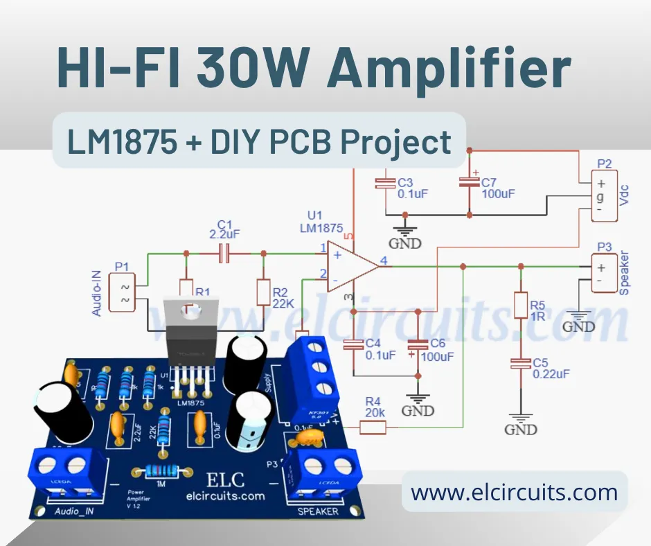
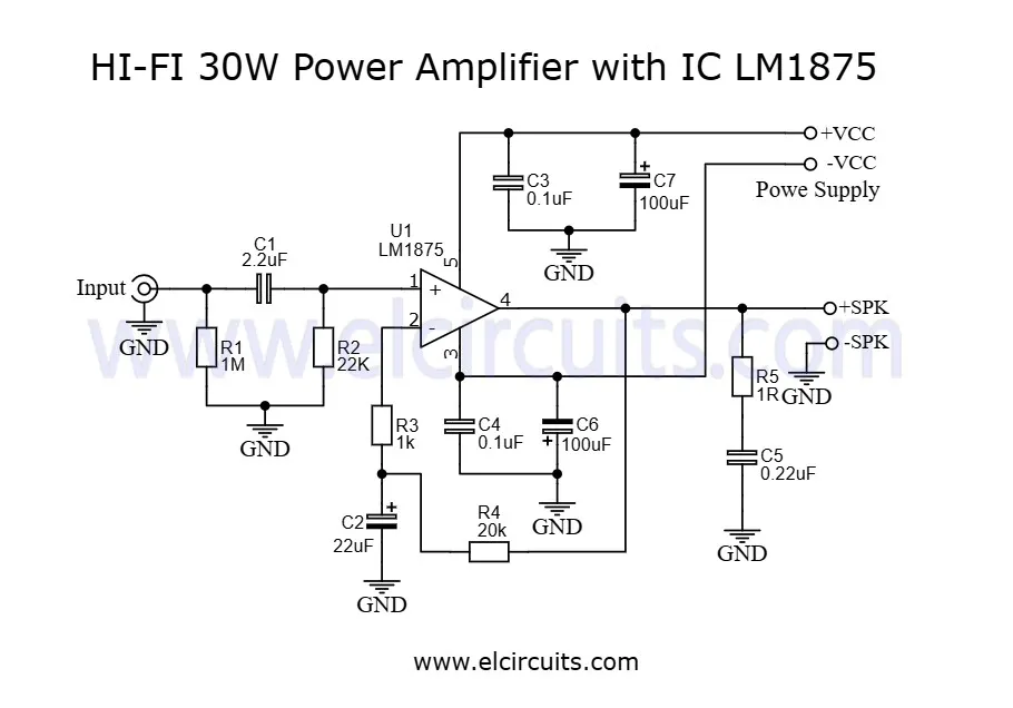
The circuit diagram in Figure 3 below showcases the elegant simplicity of this amplifier design. As you can see, there are very few external components required, which not only makes assembly straightforward but also improves reliability by minimizing potential points of failure.
This design follows a classic non-inverting amplifier configuration with a gain of approximately 21 (determined by the ratio of R4 to R3). The input is AC-coupled through C1 to block any DC component from the source, while the output is protected by R5 and C5, which form a Zobel network to ensure stability with reactive speaker loads.
⚠️ Pro Tip: When building this circuit, pay special attention to the grounding scheme. A star ground configuration, where all ground connections meet at a single point, will minimize noise and hum in your amplifier.
📚 Understanding the Circuit Operation
- Input Stage: The audio signal enters through C1, which blocks any DC voltage from the source. R1 provides a path to ground for the input bias current.
- Gain Stage: The LM1875 is configured as a non-inverting amplifier with gain determined by the ratio of R4 (20kΩ) to R3 (1kΩ). This gives us a gain of approximately 21 (1 + R4/R3).
- Output Stage: The LM1875’s output stage drives the speaker directly through C6, which blocks any DC offset from reaching the speaker.
- Stability Network: R5 and C5 form a Zobel network, which ensures stability with reactive speaker loads that can otherwise cause oscillation.
- Power Supply: C7 and C8 provide power supply decoupling, filtering out noise and ensuring clean power delivery to the IC.
🔌 Power Supply Considerations
💡 Advanced Tip: Adding a soft-start circuit to your power supply can prevent turn-on thumps and extend the life of your components by limiting inrush current.
You might also be interested in:
170W AB Class Bridge Mode Amplifier using TDA7294 IC + PCB
Looking for more power? This bridge-mode amplifier delivers impressive output.
High Fidelity 14W – 12V Power Amplifier using TDA2030 IC + PCB</a >
Need a compact amplifier for portable applications? This might be perfect.
24W Stereo Hi-Fi Audio Amplifier using TDA2616 + PCB</a >
For true stereo sound, check out this dual-channel amplifier design.
🛠️ Power Dissipation and Heat Sink
Proper thermal management is crucial for the LM1875’s performance and longevity. The IC must always be operated with a heat sink, even when not driving a load. For optimal performance, we recommend using a heat sink with a thermal resistance of 1°C/W without an insulator, assuming an ambient temperature of 25°C.
It’s worth noting that the LM1875’s output limiting circuitry has a negative temperature coefficient. This means that when the tab temperature exceeds 55°C, the maximum output power delivered to a 4Ω load may be slightly reduced. This is a protective feature to prevent thermal damage, not a flaw in the design.
🔧 Pro Tip: When mounting the LM1875 to the heat sink, use a thin layer of thermal compound to ensure efficient heat transfer. If you need to electrically isolate the IC from the heat sink, use a mica washer with thermal compound on both sides.
🧾 Component List
Semiconductors
- U1 ……… LM1875 Integrated Circuit
Resistors (1/8W)
- R1 ……… 1MΩ (brown, black, yellow, gold)
- R2 ……… 22KΩ (red, red, orange, gold)
- R3 ……… 1KΩ (brown, black, red, gold)
- R4 ……… 20KΩ (red, black, orange, gold)
- R5 ……… 1Ω (brown, black, gold)
Capacitors
- C1 …….. 2.2µF Polyester capacitor
- C2 …….. 25V 22µF Electrolytic capacitor
- C3, C4 …. 0.1uF Ceramic capacitor
- C5 …….. 0.22uF Ceramic capacitor
- C6, C7 … 70V 100µF Electrolytic capacitor
Connectors
- P1, P3 …. Screw Terminal Block: 2-Pin, 5 mm
- P2 ………. Screw Terminal Block: 3-Pin, 5 mm
Additional Components
- Printed circuit board
- Heat sink
- Enclosure box
- Solder, wires, etc.
🔧 Assembly Tips
- Component Placement: Start with the lowest profile components (resistors, diodes) and work your way up to the taller ones (capacitors, IC).
- IC Installation: Use an IC socket for the LM1875 if possible. This makes replacement easier and protects the IC from soldering heat.
- Polarity Matters: Double-check the polarity of all electrolytic capacitors and the LM1875 itself before soldering.
- Clean Connections: Ensure all solder joints are shiny and smooth. Cold solder joints can cause intermittent problems.
- Initial Testing: Before connecting speakers, test the amplifier with an oscilloscope to check for oscillations or DC offset at the output.
🔍 Troubleshooting Guide
| Problem | Possible Cause | Solution |
|---|---|---|
| No sound output | Power supply issue, incorrect wiring | Check power supply voltages, verify all connections |
| Distorted sound | Incorrect gain, oscillation, overheating | Check resistor values, look for oscillations with scope, verify heat sink |
| Hum or noise | Poor grounding, power supply noise | Implement star grounding, add power supply filtering |
| IC overheats | Insufficient heat sinking, oscillation | Improve heat sink, check for oscillations |
🖨️ Printed Circuit Board (PCB) – Download

📥 Files to Download, Direct Link:
Click on the link beside: Click Here!</a ></strong >
🤔 Dúvidas Frequentes (FAQ)
Para garantir que seu projeto seja um sucesso, compilamos algumas das perguntas mais comuns sobre este tema. Confira!
Can I use this amplifier with a single power supply instead of a dual supply? 🔽 </b >
Yes, but it requires some circuit modifications. You’ll need to create a virtual ground at half the supply voltage using a voltage divider and buffer, and then bias the input appropriately. The performance might not be as good as with a proper dual supply, but it’s definitely possible for portable applications.
Can I bridge two LM1875 amplifiers for more power? 🔽
Yes, you can configure two LM1875 ICs in a bridge configuration to approximately double the output power. However, this requires careful circuit design to ensure proper phase inversion between the two amplifiers and protection against DC offset. The load impedance also effectively doubles, so a bridge configuration driving an 8Ω speaker presents a 4Ω load to each IC.
What type of power transformer do I need for this amplifier? 🔽
For optimal performance, you’ll need a center-tapped transformer with a secondary rating of 18V-0-18V to 22V-0-22V at 2A or more. After rectification and filtering, this will give you approximately ±25V to ±30V DC, which is ideal for the LM1875. The VA rating should be at least 80VA for a single channel, or 160VA for a stereo pair.
Can I substitute the LM1875 with another IC? 🔽
The TDA2050 and TDA2030 are pin-compatible alternatives, though they have slightly different specifications. The TDA2050 is very similar in performance, while the TDA2030 has lower power capability. If you substitute, you may need to adjust some component values, particularly for the power supply and heat sink requirements.
How can I improve the performance of this amplifier? 🔽
- 1) Use higher quality capacitors in the signal path;
- 2) Implement a star grounding scheme;
- 3) Add a regulated power supply;
- 4) Use a larger heat sink with thermal compound;
- 5) Shield the input signal path to reduce noise;
- 6) Add a soft-start circuit to prevent turn-on thumps.
🎯 Conclusion
The LM1875-based amplifier represents an excellent balance between simplicity, performance, and cost. With just a handful of components, you can build an amplifier that delivers clean, powerful sound that will satisfy even discerning listeners. Whether you’re building your first amplifier or adding to your collection of DIY audio projects, this design offers a rewarding experience both in the building process and in the listening results. The modular nature of the design also makes it easy to expand into a stereo system or even experiment with bridge configurations for more power. We hope you enjoy building this project as much as we enjoyed designing it. Happy soldering, and may your music always sound its best!✨ Our Gratitude and Next Steps
We sincerely hope this guide has been useful and enriching for your projects! Thank you for dedicating your time to this content.
Your Feedback is Invaluable:
Have any questions, suggestions, or corrections? Feel free to share them in the comments below! Your contribution helps us refine this content for the entire ElCircuits community.
If you found this guide helpful, spread the knowledge!
🔗 Share This GuideBest regards,
The ElCircuits Team ⚡


