 Português
 Español
3500W AC Dimmer for 110V/220V with TRIAC TIC246 + PCB

3500W Dimmer for 110V or 220V using TRIAC TIC246M with PCB
This is a dimmable load controller circuit, its operation is based on control of the sine cycle, keeping it off during a small period of wave. And work only for a specific part of wave keeping the load with part of wave controlled by period, similar to PWM.
With this type of circuit we can control the intensity of an incandescent light, ceiling fans, resistive load, among others, through decay of the cycle regulated through a potentiometer.
The Dimmer Circuit
The 3500W Dimmer for 110V or 220V using TRIAC TIC246M with PCB circuit diagram is shown in Figure 2 below.
It uses a 16 Amp TRIAC TIC246, this is enough to handle loads up to a little over 3500W, obviously with heat sink.
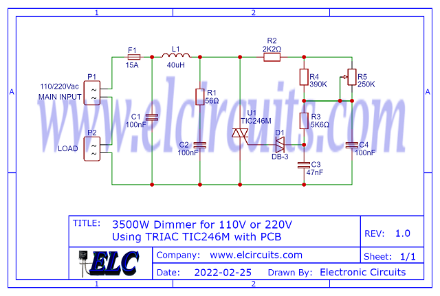
Fig. 2 – Schematic Circuit 3500W Dimmer for 110V or 220V using TRIAC TIC246M
If you need to increase the power of the circuit, you can replace the thyristor in the circuit. Using the simple formula of Ohms Law, P = V * I, through current and voltage, we can find the power of the circuit with each of the Thyristors:
- TIC246 = 16A:
- At 110V => P = 110 * 16 = 1760W
- At 220V = P = 220 * 16 = 3,520W
- TIC256 = 20A:
- At 110V => P = 110 * 20 = 2,200W
- At 220V => P = 220 * 20 = 4,400W
- TC266 = 25A:
- At 110V => P = 110 * 25 = 2750W
- At 220V => P = 110 * 25 = 5,500W
CAUTION!!!
This circuit works directly connected to the 110/220V electrical network, and has a high power load, any carelessness, or wrong connections, error in the project, or any other occasion, can lead to irreversible damage.
We are not responsible for any type of event. If you do not have enough experience to assemble this circuit, do not do it, and if you do, when testing, be sure to have the proper protections and be accompanied by someone else.
How it works
When we connect AC mains to the circuit, there is a charging of capacitor C4 through the voltage set in Trimpot RP1. When biased, there is a sending of this voltage to the DIAC through the current limiting resistor R3.
The DIAC is a bidirectionally biased diode, and is triggered when it reaches its breakdown voltage, about 30V, as it is connected to the Gate of the TRIAC. As soon as it reaches its breakdown voltage, both positive and negative pulses are activated in the Gate of the TRIAC.
However, this also charges the capacitor with reverse voltage from the negative half-cycle, and in this charging time the TRIAC stays open until the cycles compound.
This is repeated with each cycle of the AC sine wave signal from the grid, which maintains its drive and cut cycle repeatedly, leading to an output voltage lower than that of the input.
The network formed by capacitor C1 and coil L1 works as a filter to inhibit RF spurious propagation through the power network. While R1 and C2 are employed for transient reductions.
The network formed by C4 and R5 in parallel with the TRIAC, serves to prevent the TRIAC from burning out, because when the dimmer is controlling inductive loads, reverse voltage spikes are formed at the moment of switching.
Thus, the capacitor absorbs the generated overvoltage and the resistor limits the discharge current from the capacitor onto the TRIAC.
The resistor R4 connected in parallel, is used to decrease the ohmic rating of the variable resistor RV1, since the applicable value for RV1 is 150k ohms.
Since it is not easy to find this variable resistor, we made an association of resistors to get it close to 150k ohms.
The network formed by capacitor C1 and coil L1 works as a filter to inhibit RF spurious propagation through the power network.
The L1 coil consists of a small ferrite rod, 1/4″ diameter and 11/4″ long, wound with 55 turns of 28 SWG enameled copper wire.
You can be using a ferrite coil from a PC power supply to make your coil, or you can be buying a commercial 40uH coil.
Components List
- Semiconductors
- U1 ………….. TIC246 Triac *See Text
- D1 ………….. DB-3 DIAC Diode
- Resistor
- R1 ……………. 56Ω (green, blue, black, gold)
- R2 ……………. 2K2Ω (red, red, red, gold)
- R3 ……………. 5K6Ω (green, blue, red, gold)
- R4 ……………. 390Ω (orange, white, brown, gold)
- R5 ……………. 250KΩ Potentiometer
- Capacitor
- C1, C2, C4 …. 100nF / 600V Polyester Capacitor
- C3 …………….. 47nF Ceramic/Polyester Capacitor
- Miscellaneous
- P1, P2 ……… 2-pin PCB soldering terminal blocks
- F1 ……………. Fuse 15A with soldering terminal blocks
- L1 ……………. 40uH Inductor *See Text
- Others ……… PCB, heat sink, wires, etc.
Printed Circuit Board
We are offering PCB – Printed Circuit Board, in GERBER, PDF and PNG files, for you who want to do the most optimized assembly, either at home.
If you prefer in a company that develops the board, you can download the files in the Download option below.
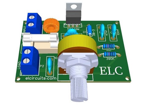
Fig. 3 – PCB – 3500W Dimmer for 110V or 220V using TRIAC TIC246M with PCB
Files to download, Direct Link:
✨ Our Gratitude and Next Steps
We sincerely hope this guide has been useful and enriching for your projects! Thank you for dedicating your time to this content.
Your Feedback is Invaluable:
Have any questions, suggestions, or corrections? Feel free to share them in the comments below! Your contribution helps us refine this content for the entire ElCircuits community.
If you found this guide helpful, spread the knowledge!
🔗 Share This Guide
Best regards,
The ElCircuits Team ⚡


