 Português
 Español
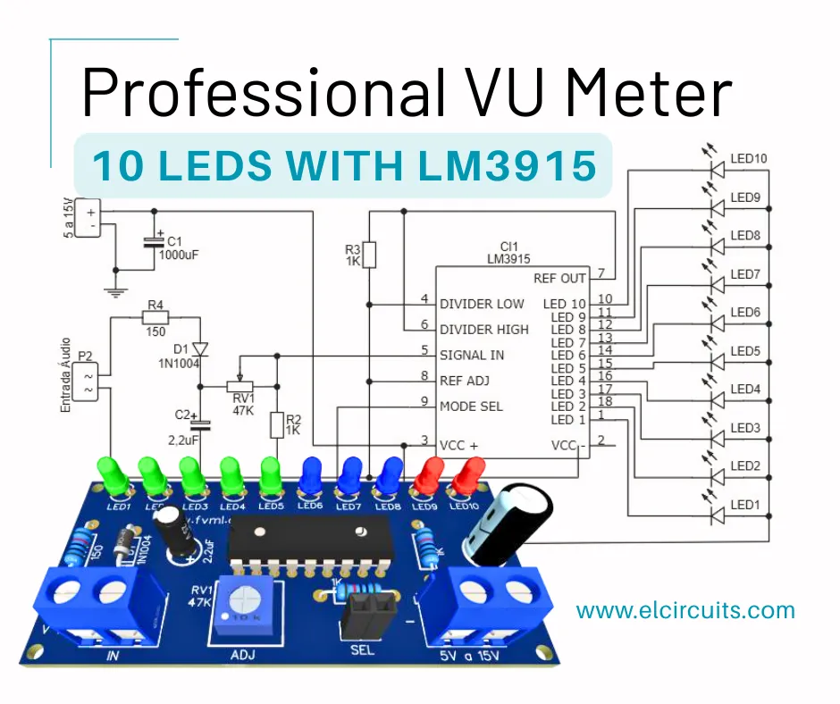
Build a Pro 10-LED VU Meter with LM3915: Ultimate DIY Guide + PCB
Hello, electronics enthusiasts!
Are you looking for a practical and visual way to monitor the audio level of your amplifier? Building a VU Meter with 10 LEDs using the LM3915 integrated circuit is an excellent choice!
This project not only enhances the aesthetics of your sound equipment but also helps to identify audio peaks that could damage speakers. The LM3915 is widely used in audio measurement systems due to its simplicity and efficiency.
In this complete guide, we'll show you step-by-step how to build the circuit, assemble the PCB, and also provide all the necessary files for you to get hands-on. Whether for use in active speakers, homemade amplifiers, or automotive projects, this VU Meter will elevate your sound level, literally. Let's go?
🎯 What is a VU Meter and Why Use One?
A VU Meter (Volume Unit Meter) is a device that measures and visually indicates the intensity level of an audio signal. It is typically represented by LED bars that light up as the sound power increases.
Reasons to use a VU Meter:
- Aesthetics and professionalism: Gives sound equipment a technical and modern look.
- Safety: Helps to avoid distortion and overloads, especially in power amplifiers.
- Diagnosis: Facilitates identification of failures in the audio channel.
- Educational: Ideal for those learning electronics or wanting to experiment with LED circuits.
The model we're presenting in this article uses the LM3915, an IC that already contains all the necessary internal logic to control 10 LEDs based on an analog signal. The great advantage is that it operates with voltage from 5 to 15V, making it perfect for automotive and home audio applications.
⚙️ How the LM3915 Works in the VU Meter
The heart of our VU Meter is the LM3915 Integrated Circuit, which internally contains a ladder of comparators that light up the LEDs according to the input level.
Features of the LM3915:
- Controls up to 10 LEDs with adjustable voltage.
- Has operation mode in bar (all LEDs below the level light up) or dot (only one LED at a time).
- Supply voltage range: 5V to 15V.
- Logarithmic scale, ideal for audio signals.
The IC interprets the voltage of the input signal and activates the LEDs sequentially, giving that famous effect of moving bars, similar to what we see in professional audio equipment.
LM3915 Operation Modes:
- Bar Mode: The LEDs light up in sequence and remain on as the audio intensity increases.
- Dot Mode: Only one LED stays on at a time, representing the current peak of the signal.
You can choose the mode by switching the key or even set a fixed mode with a jumper in place of switch 1, to simplify assembly.
About the LEDs:
You can use different colors to indicate sound intensity levels:
- Green: Low volume (0-60%)
- Yellow: Medium volume (60-80%)
- Red: High volume (80-100%)
This visual distinction facilitates quick reading and adds sophistication to the project.
🔌 Schematic Diagram of the VU Meter with LM3915
The schematic diagram is the basis for assembling your circuit and is shown in Figure 2 below. It's essential to pay attention to the polarity of the LEDs, Capacitors, and the correct side of the IC.

🔧 Step-by-Step Assembly of the VU Meter Circuit
Assembling the VU Meter is a simple task, but requires attention to detail. Before turning on the soldering iron, organize all components on the bench. A valuable tip is to check the position of each component by comparing with the schematic diagram.
Assembly steps:
- Prepare the PCB: If you're using the printed circuit board we've provided, start by fixing the resistors. They are small and should be soldered first.
- Install the LEDs: Pay attention to polarity, the shorter side (cathode) should face GND.
- Position the LM3915: If possible, use a socket for the IC. This facilitates replacement in case of error or failure.
- Solder the capacitors: C1 is essential for signal filtering. C2 is optional, but improves stability. We recommend its use.
- Connect the selector switch: If you choose to have both display modes (bar and dot), this switch allows alternating between them.
- Install the potentiometer: P1 will be your sensitivity control. Place it on the front of the panel if you want easy adjustment.
- Review everything: Before powering on, review all connections. Make sure there are no cold solder joints or shorts.
With everything assembled, the next step is to test the circuit. But wait! Don't connect directly at high volume. Let's see how to calibrate correctly in the next topic.
🔧 Adjustment and Calibration of the VU Meter
With the circuit assembled, now it's time to test and calibrate the VU Meter. This ensures that the LEDs light up at the correct audio intensities and that the system responds appropriately.
How to calibrate:
- Connect the output of your amplifier to the VU Meter input.
- Turn on the amplifier with the volume at minimum.
- Gradually increase the volume while observing the LEDs.
-
Turn potentiometer P1 to adjust sensitivity.
- If the LEDs light up too early, reduce the gain.
- If the LEDs take too long to light up, increase the gain.
- Check if the red LEDs only light up at audio peaks.
This calibration is essential because different amplifiers have varying output levels. By adjusting correctly, you ensure that the VU Meter works precisely and professionally, regardless of the equipment.
🔗 Usage Tips and Practical Applications
The VU Meter with LM3915 can be used in various applications, and its versatility allows adapting the circuit according to the project's needs.
Where to use this VU Meter:
- Active speakers: to indicate the intensity of the audio signal.
- Automotive systems: coupled to the car stereo, improves aesthetics and helps with monitoring.
- Homemade amplifiers: adds a professional and functional touch.
- Educational projects: ideal for teaching principles of analog and digital electronics.
- DIY mixing consoles: to indicate the output level of each channel.
Tips for customization:
- Change LED colors according to your preference or to facilitate reading.
- Place the circuit in an acrylic box to highlight the LEDs.
- Integrate a microcontroller if you want extra features like remote control or peak memorization.
📋 Component List
- IC 1 - Integrated Circuit LM3915
- LED1 ~ LED10 - *see text
- D1 - Diode 1N1007 - or equivalents (1N1002, 1N1004...)
- P1 - Potentiometer 47K
- C1 - Electrolytic Capacitor 2.2uf
- C2 - Capacitor *see text
- R1, R2 - Resistor 1K (brown, black, red)
- R3 - Resistor 150 Ohms (brown, green, black)
- Switch1 - General purpose switch (any model) *see text
💡 Fresh Ideas for Your Next Project
Did you enjoy this project? Then you'll love exploring other circuits we've prepared. Each one with its unique features and ideal applications!
🖨️ PCB - Printed Circuit Board
To make your life easier, in Figure 3, we provide the PCB - Printed Circuit Board files. The files are in GERBER, PDF, and PNG formats, covering all your needs, whether for a homemade assembly or to send to a professional fabrication.
And best of all: the files are available for free download directly from the MEGA server, through a direct link, without any complication or redirection!

📥 Direct Link to Download
To download the necessary files for assembling the electronic circuit, simply click on the direct link provided below:
Link to Download: PCB Layout, PDF, GERBER, JPG
🤔 Frequently Asked Questions (FAQ)
To ensure your project is a success, we've compiled some of the most common questions on this topic. Check them out!
What's the difference between the LM3915 and the LM3914? 🔽
The LM3915 has a logarithmic scale of -3dB per step, ideal for audio applications (VU meters), while the LM3914 has a linear scale, more suitable for general level meters. For a VU Meter, the LM3915 is the correct choice.
Can I power the circuit directly from the car battery (12V)? 🔽
Yes, the LM3915 works perfectly with 12V, which is within the operating range of 5V to 15V. However, it's recommended to add a voltage regulator (like the 7812) or a filter to avoid noise from the vehicle's power supply.
Is it possible to use high-brightness or RGB LEDs in this circuit? 🔽
Yes, you can use high-brightness LEDs without problems. For RGB LEDs, you'll need additional circuits to control each color separately, as the LM3915 controls only one channel per LED. An alternative is to use RGB LEDs with internal control that change color automatically.
How do I adjust the sensitivity of the VU Meter? 🔽
Sensitivity is adjusted through potentiometer P1 (47K). Turn it clockwise to increase sensitivity (LEDs will light up with weaker signals) or counterclockwise to decrease (a stronger signal will be needed to light the LEDs).
Can I connect two VU Meters for stereo (left and right)? 🔽
Yes, you can assemble two identical circuits, one for each audio channel (left and right). Each circuit will have its own LM3915 and set of LEDs. Make sure both share the same power supply to maintain consistency between channels.
✨ Our Gratitude and Next Steps
We sincerely hope this guide has been useful and enriching for your projects! Thank you for dedicating your time to this content.
Your Feedback is Invaluable:
Have any questions, suggestions, or corrections? Feel free to share them in the comments below! Your contribution helps us refine this content for the entire ElCircuits community.
If you found this guide helpful, spread the knowledge!
🔗 Share This GuideBest regards,
The ElCircuits Team ⚡


