 Português
 Español
5A Step-Down Converter 1.22V-26V Using RT8289 IC – With PCB
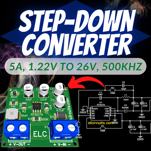
Fig. 1 – 5A, 1.22V to 26V, 500kHz Step-Down Converter Using RT8289 IC with PCB
Powerful 5A Step-Down Converter: Build a Versatile 1.22V to 26V Solution at 500kHz with RT8289 IC and PCB
This is a DC-DC 5A, 1.22V to 26V, 500kHz Step-Down Converter Using RT8289 IC, it works with a Step-Down conversion system.
This powerful chip manages to work with very few external components and provides a preset voltage between 1.22V to 26V, with 5 Amps of output current.
📖 General IC Description
The RT8289 is a step-down regulator with an internal Power MOSFET. It achieves 5A of continuous output current over a wide input supply range with excellent load and line regulation.
Current mode operation provides fast transient response and eases loop stabilization. The RT8289 provides protections such as cycle-by-cycle current limiting and thermal shutdown.
In shutdown mode, the regulator draws 25μA of supply current. The RT8289 requires a minimum number of external components, to provide a compact solution. The RT8289 is available in a SOP-8 (Exposed Pad) package.
🛠️ Features
- High Output Current up to 5A
- Internal Soft-Start
- 100mΩ Internal Power MOSFET Switch
- Internal Compensation Minimizes External Parts Count
- High Efficiency up to 90%
- 25μA Shutdown Current
- Fixed 500kHz Frequency
- Thermal Shutdown Protection
- Cycle-by-Cycle Over Current Protection
- Wide 5.5V to 32V Operating Input Range
- Adjustable Output Voltage from 1.222V to 26V
- Available in an SOP-8 (Exposed Pad) Package
- RoHS Compliant and Halogen Free
⚡ Output Voltage Setting
To define the output voltage, we use a voltage divider formed by 2 resistors, R1 and R2, this allows the FB pin of the integrated circuit to detect changes in the output voltage, and recalibrate the circuit keeping it stabilized.
To set this output voltage, we can calculate the external resistive divider, according to the equation formulated below:
- VOUT = VREF *(1 + (R1/R2))
- Where VREF is the reference voltage (type 1.222V).
- Where R1 = 10kΩ.
We exemplify in our circuit, the voltage divider is formed by R1 and R2.
✔️ General Formula:
- VOUT = VREF *(1 + R1/R2)
- Where VREF is the reference voltage (type 1.222V).
- Where R1 = 10kΩ.
✔️ For a 3.3V output, our formula would look like:
- Vout = 1,222 * (1+ (10/5.8))
- Vout = 3.328V
✔️ For a 5V output, our formula would look like:
- Vout = 1,222 * (1+ (10/3.16))
- Vout = 5,089V
✔️ For a 9V output, our formula would look like:
- Vout = 1,222 * (1+ (10/1.57))
- Vout = 9,005V
✔️ For a 12V output, our formula would look like:
- Vout = 1,222 * (1+ (10/1.13))
- Vout = 12,036V
✔️ For a 26V output, our formula would look like:
- Vout = 1,222 * (1+ (10/0.493))
- Vout = 26,009V
We may be using a trimpot instead of R2, this allows you to vary the output voltage through the Trimpot.
🔌 The Circuit Schematic
In Figure 2, below, we can see the schematic diagram of the Low Noise and High Frequency 5A DC-DC Step-Down Converter.
All circuit components are SMD, except the terminal blocks, “optional”, you can solder directly to the board. This type of SMD circuit is great to be implemented in miniaturized circuits.
It is preferable to use tantalum capacitors, but if you cannot find them, electrolytic capacitors can be used, but for more sensitive circuits, we recommend using tantalum.
The DC-DC converter supports input from 5.5V to 32V, and at the output it maintains the preset voltage completely stabilized.

Fig. 2 – Schematic 5A, 1.22V to 26V, 500kHz Step-Down Converter Using RT8289 IC
🔗 Related Content
If you liked this project, you might also be interested in these other articles:
- Symmetrical SMPS Switched Power Supply with IR2153 and IRF840 – 2x50V 350W + PCB
- Adjustable Switching Power Supply 5.1 to 40V, 2.5 Amp using L4960 + PCB
- Switched Power Supply SMPS 13.8V 10A using IR2153 IC and IRF840, with PCB
- How to Modify an ATX Power Supply to 13.6V, 22 Amperes
- Mini Switching Power Supply 5V – 24V, 3A using TNY268 with PCB
- 4A Low-Noise High-Frequency Step-Up DC-DC Converter using MAX1709 + PCB
- How ATX Power Supplies Work: Learn to Diagnose Problems in 10 Simple Steps
🖨️ Printed Circuit Board
In Figure 3, we provide the PCB – Printed Circuit Board, in GERBER, PDF and PNG files. These files are available for free download, on the MEGA server, in a direct link, without any bypass.
All to make it easier for you to do a more optimized assembly, either at home, or with a company that prints the board. You can download the files in the Download option below.
The PCB tracks are doubled, the main ones have their tracks on the bottom and top of the PCB as the current is 5 amps.
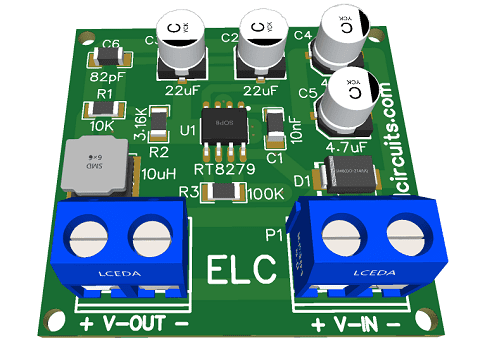
Fig. 3 – PCB 5A, 1.22V to 26V, 500kHz Step-Down Converter Using RT8289 IC
📥 Files to download, Direct Link:
Click on the link beside: GERBER, PDF and PNG files
✨ Our Gratitude and Next Steps
We sincerely hope this guide has been useful and enriching for your projects! Thank you for dedicating your time to this content.
Your Feedback is Invaluable:
Have any questions, suggestions, or corrections? Feel free to share them in the comments below! Your contribution helps us refine this content for the entire ElCircuits community.
If you found this guide helpful, spread the knowledge!
🔗 Share This Guide
Best regards,
The ElCircuits Team ⚡


