Português
 Español
How ATX Power Supplies Work – Diagnose Problems in 10 Easy Steps
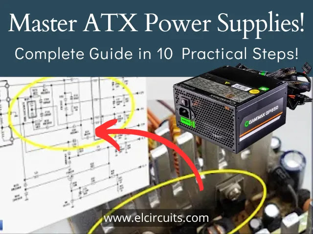
How ATX Power Supplies Work: Learn to Diagnose Problems in 10 Simple Steps
Hello, electronics enthusiasts!
ATX Switched-Mode Power Supplies have some interesting features when compared to standard Switched Mode Power Supply (SMPS).
In the ATX power supply, there are different output voltages: + 12V, + 5V, + 3.3V, -12V, -5V and 5VSB. There are some variations on these types of Power Supply, but in the general context, the pattern is this.
The way SMPS work is pretty much the same.
They control the output voltage by opening and closing the switching circuit so as to maintain the opening and closing time of this circuit, that is, the width of pulses and their frequencies, to obtain the desired voltage.
There are separate processes for everything to work smoothly. So let’s see the modular diagram to unravel the steps of these processes so that we can step by step understanding.
This is the block in modules divided by steps, to improve our understanding.
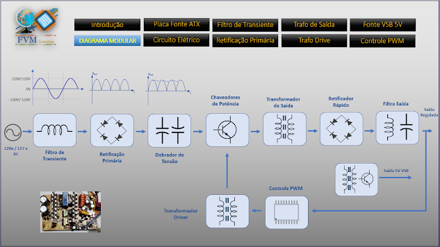
This is the block in modules divided by steps, to improve our understanding.
There are distinct processes that need to work together for everything to function properly. Let’s take a look at the modular diagram to break down each step and better understand how these processes unfold.
There are 10 basic steps involved in operating an ATX power supply, although there are additional underlying modules that are intrinsically connected to these steps.
We won’t go into too much depth here, but for those who want a more detailed explanation, we’ve included a video in Portuguese at the end of this article, created by our partner site.
So let’s understand these steps:
Step 1 – Transient Filter
Is through that stage that the voltage coming from your network, whether 110 or 220V AC should enter.
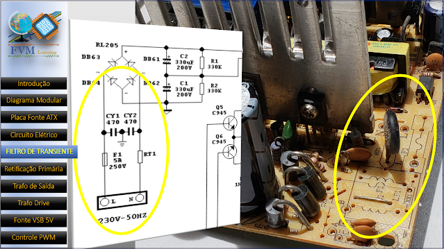
Fig. 2 – How SMPS Works – Transient Filter
This voltage goes through basic protection, fuse, that if some step ahead short, the fuse opens, avoiding to burst everything ahead, and in the same line, we have NTC (Negative Temperature Coefficient), It’s a surge current limiter, in series with the electric circuit.
In its value of ohmic resistance decreases as its temperature rises, its initial resistance is approximately 15 Ohms, which we can understand by the Ohms’ law, advantages one has in using it in series after the power supply switches it on lowers its resistance to approximately 0.5 Ohms.
EMI filters also exist, these are used to avoid high-frequency noise and a huge amount of harmonics generated by the switches that can propagate through the electrical network and cause interference in nearby electronic equipment.
Step 2 – Primary Rectification
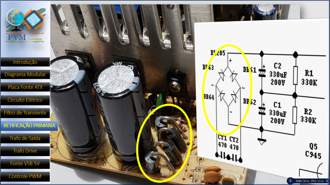
Fig. 3 – How SMPS Works – Primary Rectification
In this stage we find the rectifier bridge or an arrangement formed by four common diodes, which has the function of rectifying a full-wave voltage, that is, rectifying an alternating electric current (AC), transforming it into a continuous electric current (DC).
Step 3 – Filtration
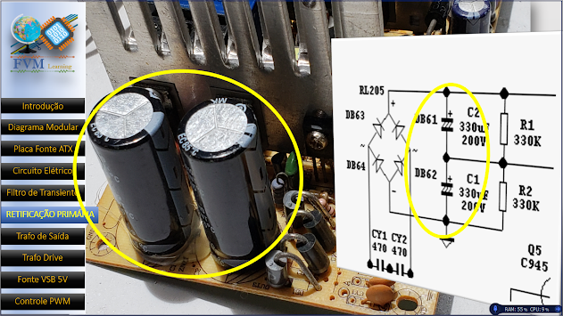
Fig. 4 – How SMPS Works – Filtration
After rectification, the DC signal, Ripples (which are small variations, capacitors are responsible for filtering and stabilization IE, a decrease of these Ripples, in the rectified voltage, this voltage rises to something around 300V, which are used in power switches, this part is fundamental to the correct stabilization of source especially if its source is of high power.
Step 4 – Power Switches
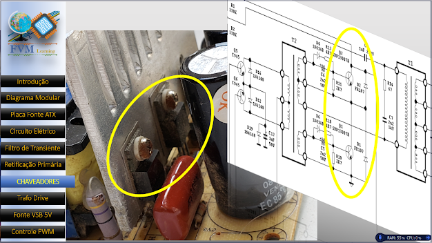
Fig. 5 – How SMPS Works – Power Switches
These switches can be Bipolar Power Transistors such as MOSFETs, or any other type, but they differ from ordinary transistors, by the type of operation in which these transistors work.
These switching transistors dissipate less power than a common working transistor in a linear source because they work as a switch on/off at high speeds, depending on the design of the source, they suffer variations that are usually between 20Khz to 100kHz.
They are directly responsible for the output voltage, and stability of that voltage, through of the commands received by the Control Circuit.
Step 5 – Output Transformer
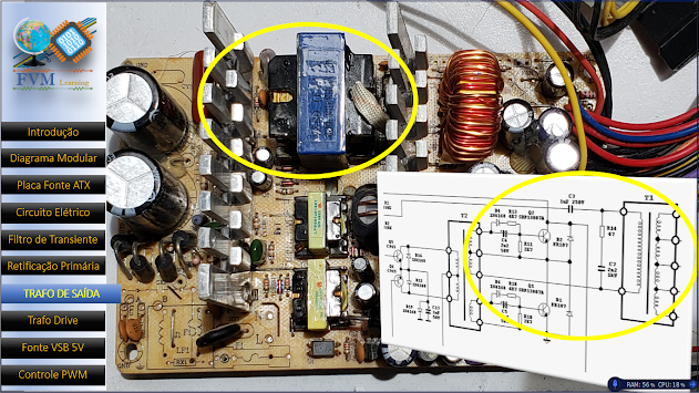
Fig. 6 – How SMPS Works – Output Transformer
The transformer is a high-frequency CHOPPER TRANSFORMER, and they also work with alternating voltage, when passing through the switches voltage will be a square wave AC type PWM, but with high frequency, not with the same frequency of 60Hz of the input voltage.
The switches work on two different levels, High and Low, when it is HIGH, voltage goes through it normally, causing a constant voltage level in the input of coil of the transformer, action of these transistors, goes from HIGH to LOW very quickly.
This will induce the winding to have the necessary voltages according to the winding and frequency placed on these switches.
Step 6 – Fast Rectifier
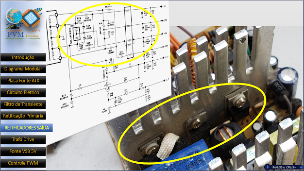
Fig. 7 – How SMPS Works – Fast Rectifier
With the voltage generated by high-frequency switches, a diode is needed to meet this demand, so we have the high-speed diodes called SCHOTTKY DIODES or fast recovery diodes since ordinary diodes would not be able to work with high-frequency voltages.
Step 7 – Output Filters

Fig. 8 – How SMPS Works – Output Filters
The inductor – This has the function of eliminating high-frequency harmonics so that they do not travel to the equipment that will be fed, imagine if these harmonics pass to a micro-controller for example, could cause undue loads and errors of reading in the control processes.
And the Capacitors – They are the ones that filter and stabilize the voltage at the output, avoiding ripples and instabilities at the output.
🔗 Related Content
If you liked this project, you might also be interested in these other articles:
- Symmetrical SMPS Switched Power Supply using IR2153 and IRF840 – 2x50V 350W + PCB
- Adjustable Switching Power Supply 5.1 to 40V, 2.5 Amp using L4960 + PCB
- Switched Power Supply SMPS 13.8V 10A using IR2153 IC and IRF840, with PCB
- How to Modify an ATX Power Supply to 13.6V, 22 Amperes
- Mini Switching Power Supply 5V – 24V, 3A using TNY268 with PCB
- 5A, 1.22V to 26V, 500kHz Step-Down Converter Using RT8289 IC + PCB
- 4A Low-Noise High-Frequency Step-Up DC-DC Converter using MAX1709 + PCB
Step 8 – Driver Transformer
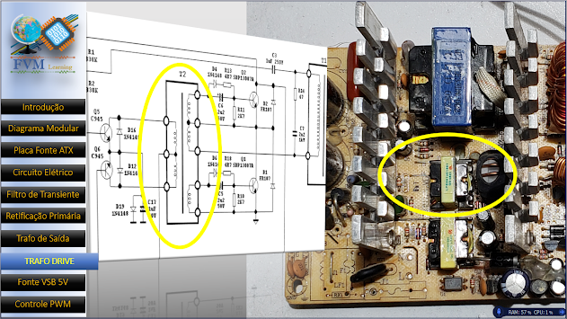
Fig. 9 – How SMPS Works – Driver Transformer
The driver transformer in this case is nothing less than one responsible for traffic of information coming from the Integrated Circuit Controller, and pass these commands to the switches, so as to bring insulation or electrical decoupling between primary and secondary.
In this topology there is a pair of transistors that also switch the Transformer Drive to receive these PWM pulses from the driver IC, passing this information to the power step we already saw in Step 4.
Step 9 – PWM control
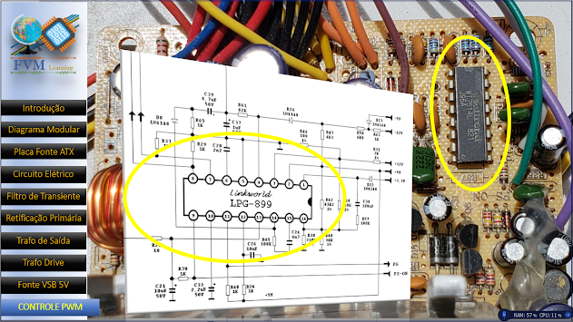
Fig. 10 – How SMPS Works – PWM control
The brain of a switched source is its PWM controller, they are dedicated integrated circuits, to perform that work, but they do not work alone, there are also current sensors, which also vary from source to source, but it is very likely that you will find in its source TL341 IC, it has the aspect of a transistor, but, it is not a transistor, it is very popular for its cost-benefit.
This circuit is connected to the output of the power supply, receives Feedback, and directs the voltage information to the IC that controls the oscillator that generates a rectangular signal whose pulse width is controlled and sent to the Transformer Drive that sends these commands to the step of power.
If the power at the output to raise the voltage tends to drop, the circuit activates the instantaneous correction in the pulse width of the switching transistors and the voltage keeps stabilized.
Step 10 – Primary Power Supply VSB
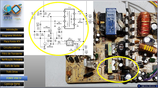
Fig. 11 – How SMPS Works – Primary Power Supply VSB
VSB stands for Voltage Standby, which is technically a power supply that keeps its output active, whenever the source power cord is connected to the mains, its capacity is approximately 2 Amps, and this depends on the total power of the source.
This active voltage line is to keep the circuit active and is necessary for when the power on button is activated through PSON, which is the start of the power supply, then the oscillator will activate the power line also powers the motherboard hardware to activate peripherals via software, keyboard, network, and so on.
For those who want a more in-depth, step-by-step explanation, we recommend watching the detailed video (in Portuguese) available on our partner’s YouTube channel. It complements this article with visual support and additional insights.
[Watch the original video in Portuguese in video below or – Click Here
✨ Our Gratitude and Next Steps
We sincerely hope this guide has been useful and enriching for your projects! Thank you for dedicating your time to this content.
Your Feedback is Invaluable:
Have any questions, suggestions, or corrections? Feel free to share them in the comments below! Your contribution helps us refine this content for the entire ElCircuits community.
If you found this guide helpful, spread the knowledge!
🔗 Share This Guide
Best regards,
The ElCircuits Team ⚡