Showing posts with label IT (Information Technology). Show all posts

Friday, August 11, 2023

Winget Upgrade Command: How to Update Applications on Windows Using CMD!

Winget Upgrade Command: How to Update Applications on Windows Using CMD!

Upgrading Your Applications Using Windows Package Manager (winget) Command on Windows

In today's fast-paced technological landscape, staying up-to-date with the latest software versions is paramount for ensuring optimal performance, security, and access to new features. 

With the introduction of the Windows Package Manager (winget) command, Microsoft has streamlined the process of updating and managing applications on Windows systems

In this comprehensive guide, we will walk you through the steps of upgrading your applications using the powerful winget command, ensuring that you harness the full potential of your software ecosystem.

Understanding the Importance of Application Updates

Regularly updating your applications is akin to servicing your car – it keeps things running smoothly and guards against potential vulnerabilities. Outdated software can expose your system to security risks, performance bottlenecks, and compatibility issues. 

By proactively upgrading your applications, you not only enjoy the latest features but also maintain a secure and efficient computing environment.

You may be interested in: 

Introducing Windows Package Manager (winget)

The Windows Package Manager, known as winget, is a command-line tool developed by Microsoft to simplify the process of installing, updating, and managing software packages on Windows systems.

With a user-friendly syntax and robust functionality, winget eliminates the need to manually search for updates or visit multiple websites to download software.

How to Install Winget?

Winget is installed by default on Windows 11, however if you are using an older version like Windows 10, you will need to install it manually.

To install Winget manually, follow these steps:

  • Open the Start menu and search for:
    Windows PowerShell.
  • Right-click on the search result and select:
    Execute as administrator.

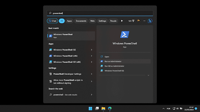
Fig. 2 - Accessing PowerShell windows as administrator

  • Type the following command and press enter:
    Invoke-WebRequest -Uri https://aka.ms/winget-cli -OutFile winget-cli.msixbundle

  • Type the following command and press enter:
    Add-AppPackage -Path winget-cli.msixbundle
That's it, now you have Winget installed on your computer!

Steps to Upgrade Applications Using winget

  • Open Command Prompt or PowerShell: Launch the Command Prompt or PowerShell on your Windows system. You can do this by searching for "cmd" or "PowerShell" in the Start menu.
  • Check for Updates: Before upgrading any applications, it's a good practice to check for available updates. Use the following command to update the package repository: 
    • winget update

  • List Installed Applications: To view the list of currently installed applications, run the command:

  • winget list

This will display a comprehensive list of installed software packages along with their unique identifiers.

How to Update Applications with "Winget Upgrade" Command?

You can be updating all the Applications installed on your Windows quickly and automatically, with a single command. All you have to do is open Command Prompt or PowerShell and type the following command:

  • winget upgrade --all
Fig. 3 - command Winget Upgrade --all cmd

Upgrade specific Applications

To upgrade a specific application, utilize the command:

  • winget upgrade <package_name>

Replace `<package_name>` with the actual name of the package you wish to upgrade. For example:

  • winget upgrade GoogleChrome

This will initiate the upgrade process for Google Chrome.

Some Tips for Making the Most of Winget

Here are some tips for getting the most out of Winget:

  • Use the "search" command to find new apps to install. For example:
    winget search <search term>
  • Use the "show" command to see detailed information about an application. For example:
    winget show <application name>
  • Use the "list" command to see all applications installed on your computer. For example:
    winget list
  • Use the "uninstall" command to uninstall an application. For example:
    winget uninstall <application name>

Advantages of Using winget for Application Upgrades

  • Efficiency: winget eliminates the need to visit various websites or application stores to manually download updates. It streamlines the process into a single, command-line interface.
  • Automated Updates: By incorporating winget into your workflow, you can schedule automated updates for your applications, ensuring that you never miss a critical upgrade.
  • Version Management: With winget, you can easily switch between different versions of a software package, allowing you to test compatibility or revert to a previous version if needed.
  • Dependency Handling: winget automatically manages dependencies, ensuring that all required components are installed or updated alongside the main application.

Conclusion

Staying up-to-date with the latest software versions is vital for a seamless and secure computing experience. Windows Package Manager (winget) simplifies the process of upgrading applications on Windows systems, allowing you to effortlessly manage your software ecosystem from the command line. 

By following the steps outlined in this guide, you can ensure that your applications are always optimized, secure, and equipped with the latest features. Embrace the power of winget and unlock a new level of efficiency in application management.

I hope you enjoyed it!!!

If you have any questions, suggestions or corrections, please leave them in the comments and we will answer them soon.

Subscribe to our blog!!! Click here - elcircuits.com!!!

My Best Regards!!!

Saturday, December 31, 2022

RJ45 Ethernet Cable Color Standard - T568A and T568B - EIA/TIA Standard

Demystifying RJ45 Ethernet Cable Color Standards: T568A vs. T568B in EIA/TIA Standard

Back in the past, a few decades ago, there were no standard regulations for the wiring of structured networks in the IT industry.

The standards for these networks were decided upon by the companies or professionals responsible for installing the wired networks. 

This lack of standardization made it difficult to maintain or modify the network structures of companies, especially when done by another company or professional.

To address this issue and with the increasing growth of technology and infrastructure for wired networks, the TIA/EIA standards were developed. 

In 1991, the TIA/EIA, 568A and 568B standards were introduced by the Electronic Industries Association (EIA) and the Telecommunications Industry Association (TIA) to standardize the electrical and electronic connections of network cables and their connections. 

The 568A standard was revised in 1994 to include Category 4 and Category 5 (UTP - Unshielded Twisted Pair) wiring, and in 2001 the EIA/TIA 568-B standard was published, covering a total of 10 different categories.

You may be interested in: 

T568A and T568B Categories

There are two different categories of TIA/EIA standards, commonly known as RJ45 Standard B and RJ45 Standard A, which are actually T568A and T568B.

These are termination standards used by Internet Providers, Backbone Infrastructure, Industrial Wiring Infrastructure, and also by small businesses and residential wiring.

However, the difference between these two categories is that the orange/white and green/white pairs, which correspond to pins 1 & 2, 3 & 6, are exchanged in the assembly of the cable, as illustrated in Figure 1 below.

Fig.1-Standard-Colors-Cable-Network-RJ45-T-568A-T-568B-Standard-EIA/TIA

It is worth remembering that even with changes to the set of pairs, when the same standards are used at both ends of the cable, the results will be the same, with direct connections at their ends.

In Table 1 below, we have the configuration of the pins and their corresponding colors, following the two standards side by side for comparison.

Sequential Table of Colors and Pinning Standard T-568A and T-568B

PinT-568AT-568B
1White/GreenWhite/Orange
2Green        Orange
3White/OrangeWhite/Green
4BlueBlue 
5White/BlueWhite/Blue
6OrangeGreen
7White/BrownWhite/Brown
8BrownBrown

The T568A standard is the widely accepted standard because it is compatible with most wiring schemes and is what I recommend for most applications.

Crossover Cable

Crossover cables, use the T-568A and T-568B standards at each end as illustrated in Figure 2 below. These categories of cables are used when we need to, for example, connect two computers or laptops without using a router or switch.

Fig. 2 - Connection of Crossover Cable Standards T-568A and T-568B

It is worth remembering that if you are still using older equipment, you should not connect crossover cables between the computer and a switch or router, as in some cases it can damage the equipment.

Now if you work with newer, more modern equipment, they use AUTO MDI/MDIX technology, which automatically identifies the connected interface and even if it is of the crossover type, there is no problem, as it automatically configures itself.

I hope you enjoyed it!!!

If you have any questions, suggestions or corrections, please leave them in the comments and we will answer them soon.

Subscribe to our blog!!! Click here - elcircuits.com!!!

My Best Regards!!!

Monday, September 14, 2020

How Switched Mode Power Supply Works - SMPS - ATX

ATX Switched-Mode Power Supplies have some interesting features when compared to standard Switched Mode Power Supply (SMPS).

In the ATX power supply, there are different output voltages: + 12V, + 5V, + 3.3V, -12V, -5V and 5VSB. There are some variations on these types of Power Supply, but in the general context, the pattern is this.
The way SMPS work is pretty much the same.
They control the output voltage by opening and closing the switching circuit so as to maintain the opening and closing time of this circuit, that is, the width of the pulses and their frequencies, to obtain the desired voltage.

There are separate processes for everything to work smoothly.
So let's see the modular diagram to unravel the steps of these processes so that we can step by step understanding.
This is the block in modules divided by steps, to improve our understanding.
 
 
There are 10 basic steps to running an ATX power supply, there are other underlying modules that are intrinsic in the steps, but, we'll not go as deep as it would be extremely great this Blogger, for those who want to watch the explanatory video with details in Portuguese. On the original post channel from YouTube.

Original Portuguese Version: Click Here

Step 1 - Transient Filter

Is through that stage that the voltage coming from your network, whether 110 or 220V AC should enter.
Transient Filter

This voltage goes through basic protection, the fuse, that if some step ahead short, the fuse opens, avoiding to burst everything ahead, and in the same line, we have the NTC (Negative Temperature Coefficient), It's a surge current limiter, in series with the electric circuit,

In it the value of ohmic resistance decreases as its temperature rises, its initial resistance is approximately 15 Ohms, which we can understand by the Ohms' law, the advantages one has in using it in series after the power supply switches it on lowers its resistance to approximately 0.5 Ohms.

EMI filters also exist, these are used to avoid high-frequency noise and a huge amount of harmonics generated by the switches that can propagate through the electrical network and cause interference in nearby electronic equipment.

Step 2 - Primary Rectification

Primary Rectification
 
In this stage we find the rectifier bridge or an arrangement formed by four common diodes, which has the function of rectifying a full-wave voltage, that is, rectifying an alternating electric current (AC), transforming it into a continuous electric current ( DC).

Step 3 - Filtration

Filtration
 
After rectification, the DC signal, Ripples (which are small variations, the capacitors are responsible for the filtering and stabilization IE, a decrease of these Ripples, in the rectified voltage, this voltage rises to something around 300V, which are used in the power switches, this part is fundamental to the correct stabilization of the source especially if its source is of high power.

Step 4 - Power Switches

Power Switches
 
These switches can be Bipolar Power Transistors such as MOSFETs, or any other type, but they differ from ordinary transistors, by the type of operation in which these transistors work, these switching transistors dissipate less power than a common working transistor in a linear source because they work as a switch on / off at high speeds, depending on the design of the source, they suffer variations that are usually between 20Khz to 100kHz, they are directly responsible for the output voltage, and stability of that voltage, through of the commands received by the Control Circuit.

Step 5 - Output Transformer

Output Transformer
 
The transformer is a high-frequency CHOPPER TRANSFORMER, and they also work with alternating voltage, when passing through the switches the voltage will be a square wave AC type PWM, but with high frequency, not with the same frequency of 60Hz of the input voltage.

The switches work on two different levels, High and Low, when it is HIGH, the voltage goes through it normally, causing a constant voltage level in the input of the coil of the transformer, the action of these transistors, goes from HIGH to LOW very quickly.

This will induce the winding to have the necessary voltages according to the winding and frequency placed on these switches.

Step 6 - Fast Rectifier

Fast Rectifier

With the voltage generated by high-frequency switches, a diode is needed to meet this demand, so we have the high-speed diodes called SCHOTTKY DIODES or fast recovery diodes since ordinary diodes would not be able to work with high-frequency voltages.

Step 7 - Output Filters

Output Filters

The inductor - This has the function of eliminating the high-frequency harmonics so that they do not travel to the equipment that will be fed, imagine if these harmonics pass to a micro-controller for example, could cause undue loads and errors of reading in the control processes.

And the Capacitors - They are the ones that filter and stabilize the voltage at the output, avoiding ripples and instabilities at the output.

Step 8 - Driver Transformer

Driver Transformer
 
The driver transformer in this case is nothing less than the one responsible for traffic the information coming from the Integrated Circuit Controller, and pass these commands to the switches, so as to bring insulation or electrical decoupling between primary and secondary, in this topology there is a pair of transistors that also switch the Transformer Drive to receive these PWM pulses from the driver IC, passing this information to the power step we already saw in Step 4.

Step 9 - PWM control

PWM control
 
The brain of a switched source is its PWM controller, they are dedicated integrated circuits, to perform that work, but they do not work alone, there are also current sensors, which also vary from source to source, but it is very likely that you will find in its source the TL341 IC, it has the aspect of a transistor, but, it is not a transistor, it is very popular for its cost-benefit.

This circuit is connected to the output of the power supply, receives Feedback, and directs the voltage information to the IC that controls the oscillator that generates a rectangular signal whose pulse width is controlled and sent to the Transformer Drive that sends these commands to the step of power.

If the power at the output to raise the voltage tends to drop, the circuit activates the instantaneous correction in the pulse width of the switching transistors and the voltage keeps stabilized.

Step 10 – Primary Power Supply VSB

Primary Power Supply VSB
 
VSB stands for Voltage Standby, which is technically a power supply that keeps its output active, whenever the source power cord is connected to the mains, its capacity is approximately 2 Amps, and this depends on the total power of the source, this active voltage line is to keep the circuit active and is necessary for when the power on button is activated through PSON, which is the start of the power supply, then the oscillator will activate the power line also powers the motherboard hardware to activate peripherals via software, keyboard, network, and so on.

If you have any questions, suggestions or corrections, please leave them in the comments and we will answer them soon.

Subscribe to our blog!!! Click here - elcircuits.com!!!

My Best Regards!!!