Showing posts with label Linear Power Supply. Show all posts

Wednesday, May 18, 2022

Electronic Resistive Load - 50A Power Supply Test with PCB

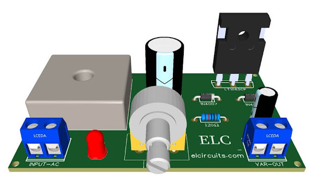
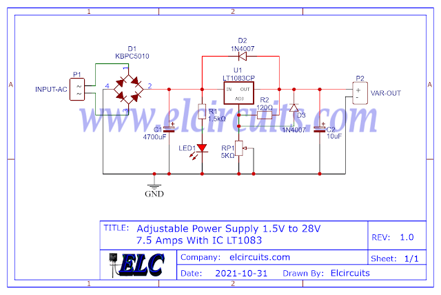
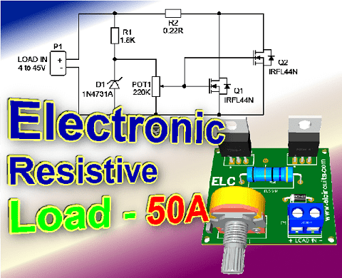
Fig. 1 - Electronic Resistive Load - 50A Power Supply Test with PCB

Efficient Power Testing: Constructing a 50A Electronic Resistive Load with PCB for Power Supply Evaluation

You know that moment when you have a power supply to fix, you do the service and the supply works, but you don't know if it will support a large load?

I came across a problem like this, and I decided to make my own resistive electronic load, and share it with our subscribers, and for you who visit us, welcome!

The circuit

The circuit is quite simple, with few components and easy to assemble, based on two power transistors Mosfet N-channel, IRL44N connected in parallel.

The circuit is capable of withstanding an initial load “for low voltage sources 4V” of 40A, and for voltage above 5V, the current is 50A, supporting voltages up to 45V.

This voltage is received and transformed into heat, and the consumption current is controlled by means of a potentiometer.

Transistor Description

Fifth Generation HEXFETs from International Rectifier utilize advanced processing techniques to achieve the lowest possible on-resistance per silicon area.

This benefit, combined with the fast switching speed and ruggedized device design that HEXFET Power MOSFETs are well known for, provides the designer with an extremely efficient device for use in a wide variety of applications.

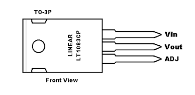
The TO-220 package is universally preferred for all commercial-industrial applications at power dissipation levels to approximately 50 watts.

The low thermal resistance and low package cost of the TO-220 contribute to its wide acceptance throughout the industry.

How it works

When turning on the electronic resistive load, a current passes through the Drain and Source taps, and this current flow is controlled by the Mosfet Gate.

For this control to happen properly, a stabilized voltage is needed at that point, which is done through the resistor R1, current limiting, in series with the zener diode, which stabilizes the voltage at the Gate.
This stabilized voltage ensures that the current not be variable when the input voltage undergoes some variation.

This stabilized voltage point is controlled by the potentiometer P1, which adjusts the voltage at the Gate of the Mosfet according to the required current.

It is worth remembering that the transistor used is a logic-type IRL44N Mosfet, not the well-known IRF44N

They differ in relation to the gate voltage, as the logic-type Mosfet triggers the Gate with low Vgs voltages from 4V, and the IRF44N does not work with such low voltages, the minimum Vgs is 7V.

The Circuit

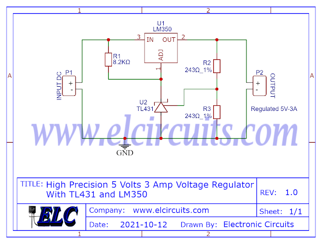
The schematic diagram of the Electronic Resistive Load - Power Supply Test!, is shown in Figure 2 below, it is a simple circuit to assemble, there are few external components to solder, however it is a circuit of great quality and stability.

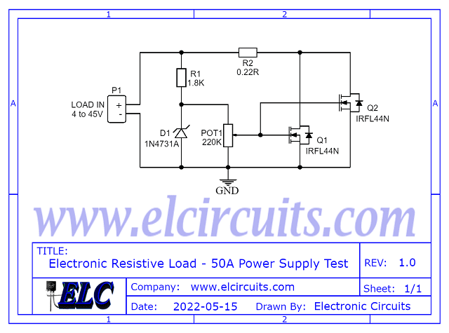
Fig. 2 - Electronic Resistive Load - 50A Power Supply Test

Component List

  • Semiconductors
    • Q1, Q2 .... IRL44N Mosfet Transistor
    • D1 ........... 1N4731 1W Zener Diode

  • Resistors
    • R1 ........ 1.8KΩ resistor (brown, grey, red, gold)
    • R2 ........ 0.22Ω resistor (red, red, silver, gold)
    • POT1 ... 220KΩ Potentiometer

  • Miscellaneous
    • P1 .... Screw Terminal Type 5mm 2-Pin Connector
    • Others .... PCB, Heat Sink, tin, wires, etc.

The PCB - Files to Download

In Figure 3, we provide the PCB - Printed Circuit Board, in GERBERPDF and PNG files. These files are available for free download, on the MEGA server, in a direct link, without any bypass. 

All to make it easier for you to do a more optimized assembly, either at home, or with a company that prints the board. You can download the files in the Download option below.

Fig. 3 - PCB Electronic Resistive Load - 50A Power Supply Test

Files to download, Direct Link:

Click on the link beside: GERBER, PDF and PNG files

I hope you enjoyed it!!!

If you have any questions, suggestions or corrections, please leave them in the comments and we will answer them soon.

Subscribe to our blog!!! Click here - elcircuits.com!!!

My Best Regards!!!

Saturday, March 26, 2022

How to Wire LEDs in 110V or 220 Volts - 6 Different Circuits! Formulas & Calculations!

Fig. 1 - How to Wire LEDs in 110V or 220 Volts - 6 Different Circuits! Formulas & Calculations!

Illuminating Insights: Wiring LEDs for 110V or 220V - Explore 6 Distinct Circuits with Formulas and Calculations!

Today we will show you 6 different ways to wire 3mm or 5mm LEDs, which are low voltage DC components, into a 110V or 220V AC voltage grid!

We can use LEDs in several ways connected to 110V or 220V power grid, knowing that some types of connections bring advantages over others, and that each type has its characteristics that best fit each specification. 

We will use some basic formulas to calculate the components in our circuit, for this we will use the capacitive reactance formula, and the Ohms Law formula.

So let's start by showing the basic formulas that we will use with the models we made in this post. 
We'll apply the basic formulas as needed, so we'll start first by determining the supply voltage. 

CAUTION! 

As simple as the circuits presented are, it is important to know that the circuit is connected to direct mains voltage, this is extremely dangerous, an oversight or design error, can cause irreversible damage.
Be cautious when handling electrical voltage, if you have no electronics/electrical experience, do not do this circuit.
If you are experienced, do it with caution, and always have someone nearby, do not handle mains-connected equipment when you are alone.
We are not responsible for any damage that happens to you or others.

The working voltage

In our country the working voltage is 110VAC, if your electrical network is 220VAC, just substitute the working voltage of your region in the formula.

It is necessary to know that our grid voltage has peak voltages, as showing in Figure 2 below, and for our safety we will use the peak to peak voltage (VPP) in our calculations.

Fig. 2 - Peak to Peak 110Vac Calculation - VPP

The calculation is determined by the mathematical equation:

  • VP = VAC * (2)

As our power grid is 110VAC:

  • VP = 110 *1.414
  • VP = 155.54VAC

If you use the 220VAC power grid:

  • VP = 220V * 1.414
  • VP = 311,08VAC

The LED

  • We will use a white LED, which in its specifications is 3.2V for 20mA, or 0.02A.

Determine the resistor resistance:

To determine the resistor resistance for the circuit, using the Ohms Law formula:
  • V = R * I
V = Voltage
R = Resistance 
I = Current

Determine the Resistor's Power:

And to determine the resistor's power we will also use Ohms' Law:
  • P = R * I²
P = Resistor Power
R= Resistor Value 
I = Current passing through the resistor.

Determine Capacitive Reactance:

Capacitive reactance is the opposition that a capacitor presents to the flow of current in AC circuits.

Capacitive reactance is represented by the notation Xc, and is expressed in ohms. To determine the capacitive reactance Xc, we will use the equation:

  • XC = 1 / (2 π  * F * C)
XC = Capacitive Reactance in Ω
π = 3,14 - Constant
F = AC Frequency in Hz
C = Capacitance in F

Knowing all the formulas that we will use in our circuits, let's start with the simplest to the most complex.

1° Circuit:

This model is the simplest we have, and it is very often used in cheap electrical extensions of those Chinese products, and also as a Pilot lamp in equipment,... 

The circuit presented has only one resistor R1, which limits the current that passes through the LED, and is connected in series with the LED, as we can see in Figure 3 below.

Fig. 3 - Wire LED in 110v or 220V Circuit 1 - ELC

Designing the Circuit

We need to determine the resistance to be used, for this we will use the ohms law formula:

General Formula:

  • V = R * I

Applying the formula to our circuit:

  • R = (VS - VL) / I 
VS = Peak mains voltage, which is 155.54Vac
VL = Voltage of the LED, which is 3.2V
IL = The LED current, which is 0.02A

Then:

  • R = (155,54 - 3.2) / 0.02
  • R = 152,34 / 0.02
  • R = 7.617R

As we know, when it comes to electronic components, there is the tolerance of the components that make up the circuit, such as the tolerance; of the resistor, the LED, and the variations "tolerance" coming from the Power grid.

For this reason, we give a tolerance margin of more or less 40% more in the load resistor, that is:

  • 7.617Ω + 40% = 3.047Ω
  • 7.617Ω + 3.047Ω = 10.6638Ω or 10.66KΩ
  • That is, the value of the closest commercial resistor, knowing that we always take the closest one with the highest value is 12KΩ.

We now need to determine the power of the resistor, for this we will use the ohms law formula:

General Formula:

  • P = R * I²

Then:

  • P = 12.000 * 0.02²
  • P = 4.8W

Project Finished - Circuit 1

We finish here the development of our circuit 1, the calculated values we will have:
  • LED1 ....... 3.2V / 20mA Light Emitting Diode
  • R1 ............ 12K / 5W Resistor for 110V. (27K to 220V).

Advantages:

  • It is a Simple and easy circuit to assemble
  • Only 2 components

Disadvantages:

  • Voltage dissipation will be on the resistor (Joule effect)
  • Consumption higher than necessary
  • Circuit operating in half wave, LED half off 
  • Short LED lifetime, reverse voltage on LED
  • Low Efficiency

2° Circuit:

This model is still quite simple, it is a circuit widely used also in cheaper electrical extensions of those Chinese products... 

The circuit presented has a resistor R1, which limits the current that passes through the LED, and a Diode, which polarizes the AC voltage coming from the power grid, which is connected in series with the LED, as we can see in Circuit 2.1 in Figure 4 below. .

We also have Circuit 2.2, which is the same circuit, but we have added a 2.2uF capacitor that serves to minimize the ripple voltage in the circuit. 

Fig. 4 - Wire LED in 110v or 220V Circuit 2 - ELC

Designing the Circuit

Just like the previous circuit, the calculations are the same, we already calculated the resistance, after all the process, it was 12K with 5W of power.

Project Finished - Circuit 2

Here we finish the development of our circuit 2, the calculated values are

  • LED1 ....... Light Emitting Diode 3.2V / 20mA
  • D1 ............ 1N4007 Diode
  • C1 ............ 2.2uF / 25V Electrolytic Capacitor (Optional)
  • R1 ............ 12K / 5W resistor for 110V. (27K at 220V).

Advantages:

  • It is a simple and easy circuit to assemble
  • Only 3 or 4 components
  • Safer circuit for LED lifetime

Disadvantages:

  • Voltage dissipation will be on the resistor (Joule effect)
  • Consumption higher than necessary
  • Circuit operating in half wave, LED half off
  • Low Efficiency

3° Circuit

This model, different from the previous one, adopts a rectifier bridge, this implies that the energy that comes to the LED, is no longer a half wave, but a full wave, which gives more brightness to the LED.

The circuit presented has a resistor R1, current limiter, and a bridge of diodes, which polarize the AC voltage that comes from the grid, and feeds the LED, as we can see in Circuit 2.1 in Figure 5 below.

We also have Circuit 2.2, which is the same circuit, but we add a 2.2uF capacitor that serves to minimize the ripple voltage in the circuit. 

Fig. 5 - Wire LED in 110v or 220V Circuit 3 - ELC

Designing the Circuit

Just like the previous circuit, the calculations are the same, we already calculated the resistance, after all the process, it was 12K with 5W of power.

Project Finished - Circuit 3

Here we finish the development of our circuit 2, the calculated values are

  • LED1 ....... Light Emitting Diode 3.2V / 20mA
  • D1 ............ 4 x 1N4007 Diode, or a diode bridge any model
  • C1 ............ 2.2uF / 25V Electrolytic Capacitor (Optional)
  • R1 ............ 12K / 5W resistor for 110V. (27K at 220V).

Advantages:

  • It is a simple circuit to assemble
  • Only 3 or 4 components
  • Full wave, which gives more brightness to the LED.
  • Safer circuit for LED lifetime

Disadvantages:

  • Voltage dissipation will be on the resistor (Joule effect)
  • Consumption higher than necessary
  • Low Efficiency

4° Circuit:

This model is simple, but works in a more efficient way, since the heat dissipation is no longer tied to the Current Limiting Resistor, which dissipated all the voltage in the previous circuits.

This circuit is widely used in Mosquito Bats, rechargeable flashlights, i.e. cheaper Chinese products. 

In this circuit we replaced the current limiting resistor with a capacitor. When a capacitor is connected to an AC source, it allows current to flow in a circuit.

With the process of successive charge and discharge of a capacitor, it gives rise to a resistance, in the passage of current in the circuit, and this resistance is called capacitive reactance. With these properties, we can use the capacitor in our circuit as a resistor.

In the case of the capacitor, all of this energy is used, because the capacitor needs to charge and discharge, it "holds" the energy and therefore does not consume it, making the circuit much more efficient. 

We also have Circuit 4.2, which is the same circuit, but we have added a 2.2uF capacitor that serves to minimize the ripple voltage in the circuit. The complete circuits are in Figure 6 below.

Fig. 6 - Wire LED in 110v or 220V Circuit 4 - ELC

Designing the Circuit

We need to determine the capacitive reactance to be used, for this we will use the Ohms' Law formula, it is exactly the formula used to figure out the resistance of R1 in the previous circuits.

Remember: The and I values are effective, so we will use the RMS voltage, not the VPP voltage. 

General Formula:

  • XC = (VS - VL) / IL 

Applying the formula to our circuit:

  • XC = (VS - VL) / I 
  • VS = Mains voltage, which is 110Vac
  • VL = Voltage of the LED, which is 3.2V
  • IL = The LED current, which is 0.02A

Then:

  • XC = (110 - 3.2) / 0.02
  • XC = 106.8 / 0.02
  • XC = 5.340Ω or 5.3K

Since we have already found out the Xreactance which is 5.340Ω or 5.3KΩ, we can now calculate the current that this capacitor will supply to our circuit. We will use the same formula as in Ohms' Law

General Formula:

  • I = VS  / XC
  • VS = Main voltagem in RMS
  • XC = Capacitive Reactance in Ω

Applying the formula to our circuit:

  • I = (VS - VL) / XC
VS = Mains voltage RMS, which is 110Vac
VL = Voltage of the LED, which is 3.2V
XC = Capacitive Reactance, which is 5.340Ω

Then:
  • I = (110 - 3.2) / 5.340
  • I = (106.8) / 5.340
  • I = 0.02A
  • I = 20mA
Knowing the resistance XC and current values in the circuit, we need to determine the capacitance of the capacitor. We will do this as follows below:

General Formula:
  • C = 1 / (2 π  * FXC

Since capacitance is usually not expressed in Farad but in a submultiple, we will use the rewritten formula, so that we can use the capacitor value in µF and make our calculations easier.

Applying the formula to our circuit:

  • C = 106 / (2 π * F * XC) 
C = Capacitance that we need to know
π = Is a constant 3.14
XC = Capacitive Reactance, which is 5.340Ω
F = Main frequency, which is 60Hz


Then:
  • C 106 / (2 * 3.14 * 60 * 5.340) 
  • C = 106 / (6.28 * 60 * 5.340) 
  • C = 106 / (376.8* 5.340) 
  • C = 106 / (2,012.112) 
  • C = 0.4969uF or 497nF
That is, the value of the closest commercial capacitor, knowing that we always take the closest one with the highest value is 560nF.

Project Finished - Circuit 4

We finish here the development of our circuit 4, the calculated values we will have:
  • LED1 ....... Light Emitting Diode 3.2V / 20mA
  • D1 ........... 1N4007 Diode
  • C1 ............ 560nF / 250V Polyester Capacitor
  • C2 ............ 2.2uF / 25V Electrolytic Capacitor (Optional)

Advantages:

  • No consumption of excess heat energy (Joule effect)
  • It is simple circuit to assemble
  • Only 3 or 4 components
  • High Efficiency
  • Safer circuit for LED lifetime

Disadvantages:

  • Circuit operating in half wave, LED half off 
  • High current in the initial steady state of the capacitor, causing those "pops" and sparks in the socket.

5° Circuit:

This model is a more complete and improved circuit, because it brings with it a diode bridge, improving efficiency even more, since the LED will no longer work for half a wave period, but for a full wave period.

This circuit is widely used in small luminaires, even in LED lamps, rechargeable flashlights, or in commercial products. 

This circuit is the junction of circuits 3 and 4, thus forming an efficient circuit, with good LED brightness, with full wave, it is almost the perfect circuit. 

The circuit presented has a diode bridge, which polarizes the AC voltage coming from the mains, which is connected in series with the LED, as we can see in Circuit 5.1 in Figure 7 below.

We also have Circuit 5.2, which is the same circuit, but we add a 2.2uF capacitor that serves to minimize the ripple voltage in the circuit.

Fig. 7 - Wire LED in 110v or 220V Circuit 5 - ELC

Designing the Circuit

First you need to determine the capacitive reactance, which was already done in the previous circuit, the capacitance is 5.340Ω or 5.3K.

Project Finished - Circuit 5

We finish here the development of our circuit 5, the calculated values we will have:
  • LED1 ....... Light Emitting Diode 3.2V / 20mA
  • D1 ........... 4 x 1N4007 Diode, or a diode bridge, any model
  • C1 ........... 560nF / 250V Polyester Capacitor
  • C2 ........... 2.2uF / 25V Electrolytic Capacitor (Optional)

Advantages:

  • It is a simple circuit to assemble
  • Only 3 or 4 components
  • Safer circuit for LED lifetime
  • No consumption of excess heat energy (Joule effect)
  • High Efficiency
  • Circuit operating in full wave, LED always on

Disadvantages:

  • High current in the initial steady state of the capacitor, causing those "pops" and sparks in the socket.

6° Circuit:

This model is more complete and, like the previous circuit, is more efficient. This circuit is widely used in small light fixtures, some LED lamps, rechargeable flashlights, and in some commercial products. 

The circuit presented is identical to circuit 5, with the only difference that we put a resistor R1, that serve to limit the capacitor inrush current. A diode bridge, which polarizes the AC voltage coming from the mains, which is connected in series with the LED, as we can see in Circuit 6.1 in Figure 8 below.

We also have Circuit 6.2, which is the same circuit, but we have added a 2.2uF capacitor that serves to minimize the ripple voltage in the circuit.

Fig. 8 - Wire LED in 110v or 220V Circuit 6 - ELC

Designing the Circuit

First you need to determine the resistance R1, the resistor value was chosen to limit the worst case inrush current to about 100mA which for safety, will be 5 times the current draw of the circuit, which will drop to less than 20mA in a millisecond as the capacitor charges.

In this case, we use ohms' law to figure out what resistor we will use.

General Formula:

  • V = R * I

Applying the formula to our circuit:

  • R = (VS - VL) / I 
  • VS = Mains voltage, which is 110Vac
  • VL = Voltage of the LED, which is 3.2V
  • IL = Inrush current, which is 0.1A or 100mA

Then:

  • R = (110 - 3.2) / 0.100
  • R = 106 / 0.100
  • R = 1,068Ω or ~1KΩ

Now, we need to determine the power of the resistor, for this we will use the ohms law formula:

General Formula:

  • P = R * I²

Then:

  • P = 1,068 * 0.02²
  • P = 0.427W

That is, the value of the closest commercial power resistor, knowing that we always take the closest one with the highest value is 1/2W.

Project Finished - Circuit 6

We finish here the development of our circuit 5, the calculated values we will have:
  • LED1 ....... Light Emitting Diode 3.2V / 20mA
  • D1 ........... 4 x 1N4007 Diode, or a diode bridge, any model
  • R1 ........... 1KΩ / 1/2W Resistor
  • C1 ........... 560nF / 250V Polyester Capacitor
  • C2 ............ 2.2uF / 25V Electrolytic Capacitor (Optional)

Advantages:

  • It is a simple circuit to assemble
  • Only 3 or 4 components
  • Safer circuit for LED lifetime
  • No consumption of excess heat energy (Joule effect)
  • High Efficiency
  • Circuit operating in full wave, LED always on

Disadvantages:

  • Can be better, by putting a resistor in parallel as a capacitor, to discharge it...

I hope you enjoyed it!!!

If you have any questions, suggestions or corrections, please leave them in the comments and we will answer them soon.

Subscribe to our blog!!! Click here - elcircuits.com!!!

My Best Regards!!!

Sunday, March 6, 2022

1.5V to 28V, 7.5 Amps Adjustable Symmetric Power Supply using IC LT1083 with PCB

Fig.1 - 1.5V to 28V, 7.5 Amps Adjustable Symmetric Power Supply using IC LT1083 with PCB

Versatile Power at Your Fingertips: Build an Adjustable 1.5V to 28V, 7.5 Amps Symmetric Power Supply with IC LT1083 and PCB

This is a power supply designed to be used in a technical bench, based on the LT1083 integrated circuit, which is an adjustable 3-terminal positive voltage regulator.

Which provides a current of 7.5A in a variable output voltage range of 1.5 to 28V, and even has short circuit and over temperature protection.

The Circuit provides a symmetrical output, which pleases all of us engineers, technicians and designers, this type of power supply, as it brings us great efficiency for application in technical benches, mainly for testing audio amplifiers.

LT1083 IC Description

The  LT1083  positive  adjustable  regulator  is designed to provide  7.5A with higher efficiency than currently  available  devices. 

In Figure 2 - You'll find the description of the input, output and ground pins. There are other types of encapsulation, as this TO - 3P is the most common.

Fig. 2 - Pinout LT1083

All  internal  circuitry  is designed to operate down to 1V input to output differential, and the dropout voltage is fully specified as a function of load current.

Dropout is guaranteed at a maximum of 1.5V at  maximum  output  current,  decreasing  at  lower  load currents. 

On-chip trimming adjusts the output voltage to 1%. The current limit is also trimmed, minimizing the stress on both the regulator and power source circuitry under overload conditions.

The LT1083  series  devices  are  pin  compatible  with  older three terminal  regulators. A 10μF  output  capacitor  is required on these new devices; however, this is usually included in most regulator designs.

Unlike  PNP  regulators,  where  up  to  10%  of  the  output current is wasted as quiescent current, the LT1083 quiescent current flows into the load, increasing efficiency.

Features

  • Three-Terminal 3.3V, 3.6V, 5V, 12V or Adjustable
  • Output Current of 3A, 5A or 7.5A
  • Operates Down to 1V Dropout
  • Guaranteed Dropout Voltage at Multiple Current Levels
  • Line Regulation: 0.015%
  • Load Regulation: 0.1%
  • 100% Thermal Limit Functional Test
  • Adjustable Versions Available

How the Circuit Work

The circuit operation is quite simple, and its operation is applied with an artifice that we did to join two adjustable power sources into one.

Since we don't have "as far as I know", a regulator of the same negative line, like what happens with the regulators LM317, LM7812 and etc.

The bridges of diodes KBPC5010 D1 and D4, are responsible for rectifying the circuit, this diode bridge is able to support currents up to 50A

I know it's an exaggeration, but it was what I had here, you can be putting with lower current, as the KBPC1510, for 15A, or the KBPC1010 for 10A.

The capacitors C1 and C3, are electrolytic capacitors responsible for filtering the circuit, we use them of 10,000uF, but if you don't have one you can put one of 8,000uF. Remembering that they have to be able to avoid Ripple in the power supply.

The resistors R1 and R3 are the limiters for LED1 and LED2, which are used as voltage signaling for the two sources.

The voltage that comes already rectified and filtered enters the Positive Voltage Regulators, as we can see in the circuit, they are identical circuits, and through the double potentiometer the output voltage regulation is done, ranging from 1.5V to 28V.

The diodes D2, D3, D5, and D6, are for reverse voltage protection that can arise from the circuit and damage the Regulators, and the diodes protect these voltages in the regulators.

The resistors R2 and R4, are responsible for the Feedback voltage, or feedback, they keep the output voltage stable, they are resistors that if you have conditions, put the ones with low error percentage, such as precision resistors with 1%.

And finally, the capacitors C2 and C4, are for spurious filter, if you can afford it, it is preferable tantalum capacitors. 

The Circuit Diagram

The complete schematic diagram of the power supply is shown below in Figure 2, it is a simple but complete adjustable symmetric power supply.

Fig. 3 - Schematic Diagram 1.5V to 28V, 7.5 Amps Adjustable Symmetric Power Supply using IC LT1083 

The Power Transformer

The transformer must be symmetrical with center tape open, this means that it will to have two independent winding: "2 Wire + 2 Wire", as illustrated in Figure 4 below. 

Fig. 4 - Symmetrical Transformer with Independent secondary winding

The transformer must be able to supply 8A at the symmetrical output. The primary voltage, “input voltage”, must correspond to the voltage in your area; 110V or 220Vac

The secondary voltage, “output voltage”, should be 21Vac in each coil, because after rectification it will supply the circuit with 30Vdc.

Component List

  • Semiconductors
    • U1, U2 .................. LT1083 Voltage Regulator  
    • D1, D4 .................. KBPC5010 - 50A Rectifier Bridge *See Text
    • D2, D3, D5, D6 .... 1N4007 Diode Rectifier 
    • LED1, LED2 ........ Light Emitter Diode (General Use)

  • Resistors
    • R1, R3 ....... 2K7Ω 1/8w Resistor (red, violet, red, gold
    • R2, R4 ....... 120Ω 1/8w Resistor (brown, red, brown, gold
    • RP1 ........... 5KΩ Double Potentiometer 

  • Capacitors
    • C1, C3 ........ 10.000uF - 45V Electrolytic capacitor 
    • C2, C4 ........ 10uF - 45V Electrolytic capacitor 

  • Miscellanies
    • P1, P2 ........ Connector 2 screw terminal 5mm 2 Pins
    • P3 .............. Connector 3 screw terminal 5mm 3 Pins
    • Others ....... Wires, Power Transformer, Solders, pcb, heat sink, etc.

Printed Circuit Board - Download

We provide the files with the PCB, the schematic, the PDF, GERBER and JPG, PNG and provide a direct link for free download and a direct link, "MEGA".

Fig. 5 - PCB - 1.5V to 28V, 7.5 Amps Adjustable Symmetric Power Supply using IC LT1083

Click on the direct link to download the files: Layout PCB, PDF, GERBER, JPG

I hope you enjoyed it!!!

If you have any questions, suggestions or corrections, please leave them in the comments and we will answer them soon.

Subscribe to our blog!!! Click here - elcircuits.com!!!

My Best Regards!!!

Thursday, December 2, 2021

High Precision 5 Volts 3 Amp Voltage Regulator Circuit using TL431 + PCB

Circuits with a high level of sensitivity require a stable supply, they are generally difficult to be powered by power supplies, due to the high level of sensitivity needed to provide stable voltage in the circuit.

However, we are introducing a stabilized power supply with an accurate output to power any sensitive circuit, such as microcontroller circuits, microprocessor circuits, RF transmission, PICs, and so on.

Today we are going to build a very precise circuit, which uses a very well-known component that is widely used in SMPS power supplies, especially ATX PC power supplies, “which looks more like a transistor”.

The 3-Pin TL431 Integrated Circuit, It offers better stability, less temperature deviation (VI (dev)) and less reference current (Iref) for greater system accuracy.

You may be interested in: 

The TL431 device is an adjustable tap regulator with thermal stability specified in the applicable automotive, commercial, and military temperature ranges.

The output voltage can be set to any value between Vref (approximately 2.5V) to 36V, with two external resistors. These devices have a typical output impedance of 0.2 Ω.

The active output circuitry provides a very crisp activation characteristic, making these devices excellent replacements for Zener diodes in many applications such as integrated regulation, tunable power supplies and switched power supplies.

Characteristics

  • Reference voltage tolerance at 25°C
  • 0.5% (class B)
  • 1% (class A)
  • 2% (standard class)
  • Adjustable output voltage: Vref to 36V
  • Operation from -40 °C to 125 °C
  • Typical temperature deviation (TL43xB)
  • 6 mV (temperature C)
  • 14 mV (I Temp, Q Temp)
  • Low output noise
  • 0.2 Ω typical output impedance
  • Sink current capacity: 1 mA to 100 mA
  • Application
  • Adjustable voltage and current reference
  • Secondary lateral adjustment in Flyback SMPSs
  • Zener Replacement
  • voltage monitoring
  • Comparator with integrated reference

In Figure 2 below, we have the schematic diagram of the High Precision Voltage Regulator Circuit with TL431 IC, the LM350 IC, provides a current of up to 3 Amps.

Fig. 1 - High Precision 5 Volts 3 Amp Voltage Regulator Circuit - TL431

With the TL431 IC, they provide a precise 5V output, which is often necessary for precision microcontrollers, sensitive equipment, that require a stabilized voltage, this circuit is ideal for that.

The power supply must provide a current of at least 3 Amps. Its input voltage must be greater than 7 Volts, to avoid overheating the LM350 IC, voltages no greater than 15V must be used.

Components List

  • CI 1 ......... Voltage Regulator Circuit LM350
  • CI 2 ......... Adjustable Regulator Circuit TL431
  • R1 ........... 8K2Ω Resistor (grey, red, red)
  • R2, R3 ..... Precision resistor 243Ω 1% (red, yellow, orange, black, brown)
  • P1, P2 ..... Soldering terminals on 2-pin PCI
  • Others ..... Printed Circuit Board, tin, wires, etc.

Download

We provide the files with the PCB, the schematic, the PDF, GERBER and JPG, PNG and provide a direct link for free download and a direct link, "MEGA".

Fig. 2 - High Precision 5 Volts 3 Amp Voltage Regulator Circuit - TL431

Click on the direct link to download the files: Layout PCB, PDF, GERBER, JPG

If you have any questions, suggestions or corrections, please leave them in the comments and we will answer them soon.

Subscribe to our blog!!! Click here - elcircuits.com!!!

My Best Regards!!!

Monday, November 29, 2021

Symmetrical Power Supply for Power Amplifiers using Calculation + PCB

Fig. 1 - Symmetrical Power Supply for Power Amplifiers

For power amplifier lovers, who build their own audio power amplifiers, here is a good full wave rectifier linear symmetric power supply that will meet the power demand without leaving anything to be desired in terms of stability.

This power supply is designed for amplifiers with power up to 2500W, it will work without any problems with great stability.

Most power amplifier circuits require a symmetrical power supply, and what differs from each other is always the power required from the supply.

As we know, a good power supply with good filtering will determine the quality and final power of your amplifier.

You may be interested in: 

The complete schematic diagram of the power supply is shown below in Figure 2, it is a simple but complete power supply.

Fig.2 - Electrical schematic Symmetrical Power Supply for Power Amplifiers


However, it is worth remembering that for each amplifier power range, we can assemble a type of power supply according to the power of your amplifier.

We are presenting 3 different configurations to exemplify the different types of power amplifiers.

There are 3 examples of simplified formulas for you to calculate the  power supply Current and Voltage according to the power of your amplifier.

Remembering that the PCB printed circuit board is the same for all configurations.

Configuration 1:

In this configuration, we can use amplifiers that have a total power up to 400W

We need to calculate the maximum power supply current, considering 45V supply, and the maximum power of 400W. Calculating ohms Law: P = V * I
  • I = P / V 
  • I = 400/45 
  • I = 8.88A
Now you need to stipulate the maximum ripple allowed in your design, in this case: If you set the maximum ripple voltage to 5%!
  • V_ripple = V_ps * 5%
  • V_ripple = 45V * 5%
  • V_ripple  = 2.25V
Once the maximum ripple voltage has been stipulated, we need to calculate the capacitor for that ripple at 5% of the source, "You may be calculating the percentage that best suits your design."

Capacitor Calculation Formula : C = I / F * V_ripple 
  • C = 8.88 / 120 * 2.25
  • C = 8.88 / 270
  • C = 0.032888 = > C = 32.888X10^-6 = 32.888uF
As our board was designed to support 6 capacitors. We can divide the entire value into uF and divide by 6 Capacitors.
  • C_individual = 32.888 / 6
  • C_individual  = 5.481uF

For a closer commercial capacitors value, we have:
C_individual = 6.800uF / 63V

  • 6 x 6.800uF Capacitor
  • 15A rectifier bridge

Configuration 2:

In this configuration, we can use amplifiers that have a total power up to 1200W

We need to calculate the maximum power supply current, considering 75V supply, and the  maximum power of 1200W. Calculating ohms Law: P = V * I
  • I = P / V 
  • I = 1200/75 
  • I = 16A

Now you need to stipulate the maximum ripple allowed in your design, in this case: If you set the maximum ripple voltage to 5%!
  • V_ripple = V_ps * 5%
  • V_ripple = 75V * 5%
  • V_ripple  = 3.75V

Once the maximum ripple voltage has been stipulated, we need to calculate the capacitor for that ripple at 5% of the source, "You may be calculating the percentage that best suits your design."

Capacitor Calculation Formula : V_ripple = I / F * C
  • C = I / F * V_ripple 
  • C = 16 / 120 * 3.75
  • C = 16 / 450
  • C = 0.035555 = > C = 35.555X10^-6 = 35.555uF

As our board was designed to support 6 capacitors. We can divide the entire value into uF and divide by 6 Capacitors.
  • C_individual = 35.555 / 6
  • C_individual  = 5.925uF

For a closer commercial capacitors value, we have:
C_individual = 6.800uF / 100V

  • 6 x 6.800uF Capacitor
  • 25A rectifier bridge

Configuration 3:

In this configuration, we can use amplifiers that have a total power up to 2500W

We need to calculate the maximum power supply current, considering 95V supply, and the maximum power of 2500W. Calculating ohms Law: P = V * I
  • I = P / V 
  • I = 2500/95 
  • I = 26A

Now you need to stipulate the maximum ripple allowed in your design, in this case: If you set the maximum ripple voltage to 5%!
  • V_ripple = V_ps * 5%
  • V_ripple = 95V * 5%
  • V_ripple  = 4.75V

Once the maximum ripple voltage has been stipulated, we need to calculate the capacitor for that ripple at 5% of the source, "You may be calculating the percentage that best suits your design."

Capacitor Calculation Formula : C = I / F * V_ripple 
  • C = 26 / 120 * 4.75
  • C = 26 / 570
  • C = 0.045614 = > C = 45.614X10^-6 = 45.614uF
As our board was designed to support 6 capacitors. We can divide the entire value into uF and divide by 6 Capacitors.
  • C_individual = 45.614 / 6
  • C_individual  = 7.602uF

For a closer commercial capacitors value, we have:
C_individual = 10.000uF / 200V

  • 6 x 10.000uF Capacitor
  • 40A rectifier bridge

Download

We provide the files with the PCB, the schematic, the PDF, GERBER and JPG, PNG and provide a direct link for free download and a direct link, "MEGA".

Click on the direct link to download the files: Layout PCB, PDF, GERBER, JPG

If you have any questions, suggestions or corrections, please leave them in the comments and we will answer them soon.

Subscribe to our blog!!! Click here - elcircuits.com!!!

My Best Regards!!!

Tuesday, November 2, 2021

Adjustable Power Supply 1.5V to 28V, 7.5 Amps using LT1083 IC + PCB

Fig. 1 - PCB Adjustable Power Supply 1.5V to 28V, 7.5 Amps With IC LT1083 

Para versão em Português, Clique Aqui!

Today we present an adjustable bench power supply from 1.5V to 28V with 7.5 amps of current, very easy to assemble, with few external components, but very functional and robust.

The circuit is based on the LT1083 integrated circuit, a 3-terminal adjustable positive voltage regulator that delivers 7.5A of current over a variable output voltage range of 1.5 to 28V with higher efficiency than currently available devices.

Each internal circuit is designed to operate with a difference of up to 1V between input and output. The guaranteed voltage drop is set to a maximum of 1.5V at maximum output current.

The internal control system adjusts the output voltage by plus or minus 1%.

You may be interested in: 

In Figure 2 - you will find the description of the input, output and ground pins. There are also other types of encapsulation, as this TO - 3P is the most common.

Fig. 2 - Pinout LT1083

The schematic shown in Figure 3 is quite simple and similar to the schematics we have shown here on our website before, such as LM350, LM338, LM317 and others, always following the line of simplicity and ease of assembly.

Fig. 3 - Schematic diagram of adjustable power supply LT1083

All LT1083 series voltage regulators are pin-compatible with the more familiar three-terminal voltage regulators, as mentioned above. These devices require a 10 μF output capacitor, which is usually included in most regulator designs.

Unlike PNP regulators where up to 10% of the production current is wasted as quiescent current, the LT1083 flows quiescent current to the load, increasing efficiency.

Features

  • 7.5A output current 
  • Three terminals pin-compatible
  • Operates down to 1V loss
  • Guaranteed cut-off voltage at various current levels
  • Line regulation: 0.015%
  • Load regulation: 0.1%
  • 100% Thermal Limit Functional Test

Applications

  • High Efficiency Linear Regulators
  • Adjustable voltage regulators Constant current regulators
  • Battery Chargers
  • Desktop power supplies

Component List

  • IC .......... LT1083Voltage Regulator Integrated Circuit 
  • D1 ......... KBPC1510 Bridge Rectifier diodes for 15 Amps or more as KBPC5010 for 50A
  • C1 ......... 4.700uF - 50V Electrolytic capacitor 
  • C2 ......... 10uF - 50V Electrolytic capacitor 
  • R1 ......... 120 ohm -1/4W Resistor - (brown, red, brown, gold)
  • R1 ......... 1.5K ohm -1/4W Resistor - (brown, green, red, gold)
  • P1 ......... 5K ohms potentiometer
  • P1, P2 ... Screw Terminal Type 5mm 2-Pin Connector
  • Others ... Wires, solders, printed circuit board, etc.

Download

We provide the files with the PCB, the schematic, the PDF, GERBER and JPG, PNG and provide a direct link for free download and a direct link, "MEGA".

Click on the direct link to download the files: Layout PCB, PDF, GERBER, JPG

If you have any questions, suggestions or corrections, please leave them in the comments and we will answer them soon.

Subscribe to our blog!!! Click here - elcircuits.com!!!

My Best Regards!!!

Thursday, October 21, 2021

Adjustable Power Supply 1.2V to 37V, 6A, Short Circuit Protection using LM317 and TIP36 + PCB

Fig. 1 - Schematic diagram Adjustable power supply circuit with short circuit protection

Para Versão Original em Português, Clique Aqui!

This is an adjustable power supply circuit from 1.2V to 37V and 6 amps of current, with short circuit protection, equipped with adjustable positive voltage stabilization circuits of three terminals LM317, plus a booster circuit, using the TIP36C, which is an inexpensive power transistor.

What makes this power supply special is the implementation of a short-circuit protection circuit, for which a BD140 PNP transistor is used.

You may be interested in: 


How the circuit works

Resistor R1, which is a load sensing resistor, receives a small current flowing through it. As long as the current in the output circuit does not reach a certain current calculated through R1, the circuit behaves like a normal voltage regulator, because at small "calculated" currents there is no voltage drop in the load sensing resistor, so the Boosters TIP36C transistor does not trip.

As the current in the circuit increases, the voltage across resistor R1 increases. When this voltage reaches about 0.6 V, the "transistor cut-off voltage", the power transistors turn on and current flows through them, with the threshold determined by the maximum current supported by the power transistors.

However, we have implemented a current protection circuit that consists of a circuit equipped with a BD140 transistor with a resistor that acts as a current sensing resistor that serves to polarize the transistor and, depending on the value detected, limit the output current of the entire circuit according to a simple Ohm's Law formula that serves to set this threshold current.

Formula 1st Ohm's Law

The 1st Ohm's Law states that the potential difference between two points of a resistor is proportional to the electric current flowing in it, and that the ratio of electric potential to electric current is always constant for ohmic resistors. The formula is as follows: V = R * I
  • V - Voltage or electric potential
  • R - Electrical resistance
  • I - Electrical current

Knowing Ohm's Law, we can now calculate the values of the load sense resistors that activate the power stage and the bias resistors of the protection transistors that form the short circuit protection circuit.

Calculating the load resistors

First, we need to know the current of the LM317 voltage regulator, which is 1.5 amps according to the datasheet.

LM317 = 1.5A
Let us calculate R1. We know that using Ohm's law, we get the following expression:
  • V = R * I
  • V = The cut-off voltage of transistors Q2 and Q3 TIP36C is 0.6V. This is the cut-off range of the transistor. Let us call Q2 and Q3 of Qeq

I = This is the current of the regulator IC1. Let us set the operating current of IC1 to 600mA, which is 0.6A. This current is enough for the IC to work unhindered.

Then:

  • R1 = Vbe_Qeq / I_CI1
  • R1 = 0.6V / 0.6A
  • R1 = 1 Ohm

Calculation of the protection circuit resistance

Similarly, we need to know the total current of the selected power supply so that there is an interruption in this range. Our power supply for 6 amps.

Power supply = 6A
Let us calculate R2. We know that Ohm's law gives us the following expression:

  • V = R * I
  • V = The cut-off voltage of the transistor Q1 is 0.6 V. "This is the cut-off range of the transistor".
  • I = The total current of the power supply, which is 6A.

Then:

  • R1 = Vbe_Q1 / I_ps
  • R1 = 0.6V / 6A
  • R1 = 0.1 Ohm

Current of the power transistors

Q2 + Q3 = 25A + 25A = 50A

However, the total power of the TIP36C transistor is 125W, which means it operates at a current of 25A to 5V. Remember the above formula, P = V * I;
  • P = 5V * 25A = 125W.

For this circuit with a maximum voltage of 37V and transistors with a maximum power of 125W, we look as follows:
  • Pmax = V * I:
  • Imax = P / V = > Imax = 125W / 37V = > Imax = 3.37A
  • How are two transistors together Imax = 6,74A

Therefore, our circuit works with two TIP36C transistors to get 6 amps at the output.

Figure 2 shows the schematic of the adjustable power supply circuit with short circuit protection. Those who follow us already know this circuit very well, the difference is exactly in the implementation of the protection circuit, as we can see below.
Fig. 2 - Schematic diagram Adjustable power supply circuit with short circuit protection

Components List

  • CI1 ................ Voltage Regulator LM317
  • Q1 ................. PNP Transistor BD140
  • Q2, Q3 .......... Power Transistor PNP TIP36C
  • D1 ................. Bridge Rectifier 50A - KBPC5010
  • D2, D3 .......... Rectifier Diode 1N4007
  • R1 ................. Resistor 2W / 1Ω
  • R2, R4, R5 ... Resistor 5W / 0.1Ω
  • R3 ................ Resistor 1/4W / 220Ω
  • C1 ................ Electrolytic Capacitor 5600uF - 50V
  • C2, C3 .......... Polyester/Ceramic Capacitor 0.1uF or 100nF
  • RV1 .............. Potentiometer 5KΩ
  • P1, P2 ........... Screw Terminal Type 5mm 2-Pin Connector
  • Others .......... Wires, solders, printed circuit board, etc.
Source: fvml.com.br

Download

We provide the files with the PCB, the schematic, the PDF, GERBER and JPG, PNG and provide a direct link for free download and a direct link, "MEGA".

Click on the direct link to download the files: Layout PCB, PDF, GERBER, JPG

If you have any questions, suggestions or corrections, please leave them in the comments and we will answer them soon.

Subscribe to our blog!!! Click here - elcircuits.com!!!

My Best Regards!!!