 Português
 Español
Long Range FM Transmitter 2.5 KM Using 2N3866 Transistor With PCB
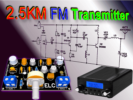
2.5KM FM transmitter, using transistor 2N3866 with PCB
Ultimate Guide: Building a Powerful 2.5KM FM Transmitter with 2N3866 Transistor and PCB
This is a simple FM transmitter, with great range, being able to reach more than 2.5 km of distance, using a suitable antenna, powered by a power supply or a 12Vdc battery.
The circuit has a frequency range that can be tuned between 88 and 108 MHz, and is quite stable, and can be used for small audio transmission links, or as community radio, and with great audio quality.
📶 The Transmitter
The FM – Frequency Modulated transmitter circuit is a wireless device that operates in a high frequency range.
It can transmit audio signals to atmosphere through electromagnetic waves, and can be received by an FM receiver circuit tuned to same frequency as the transmitter, to reproduce signals from; songs, voice, musical instruments, etc. on the FM receiver.
⚠️ Caution!⚠️
For each Country, Region, State… There are Laws on broadcasting, telecommunications, audio and video transmission, etc.
Do not use telecommunications equipment without authorization from entities responsible for transmitting Radio Frequencies.
Electronic Circuits teaches electronics applied to various segments, with the aim of improving knowledge, we do not support or take responsibility for any type of illegal operation.
For any operation with RF, we recommend looking for competent regulatory agencies, seeking certification and/or legalization.
🛠️ Characteristics!
- High sensitivity of audio pickup
- 12V to 16Vdc supply voltage
- Simple circuit to assemble
- Great range, about 2.5km
- Easy assembly
🧮 Circuit Operation
The circuit uses two RF transistors; Q1 2N2218 used as RF oscillator, and transistor Q2 2N3866, used for power stage.
The decouple electrolytic capacitor C1, receives the audio signal, who comes from a signal source, which can be a soundboard, a USB audio card, a musical instrument, or any other signal source.
This modulated signal is sent to the base of transistor Q1, it works as an oscillator circuit, trimmer VC1 in parallel with coil L1, adjusts circuit operating frequency.
Transistor Q2 works as power stage of the transmitter, it amplifies the RF signal generated by Q1, and sends it to the output, composed by the antenna.
Trimmers VC2 and VC3 connected to the antenna, adjust the impedance of the antenna coupled to the output, which we must adjust for better impedance matching, and to obtain the best signal at the output.
🔦 Applications!
- Audio transmitter
- Audio link for instruments
- Wireless microphones
- Spy Microphone
- Homemade FM radio
🔌 Schematic Diagram
The schematic diagram of the 2.5 km FM Transmitter is in Figure 2 below. As we can see, it is a very simple circuit, however, it is not recommended for those who have no experience with electronic circuit assembly.
It is recommended to mount this circuit in a metal box, if you do not have a metal box, glue aluminum foil on the walls of the box to shield the entire circuit from external interference.
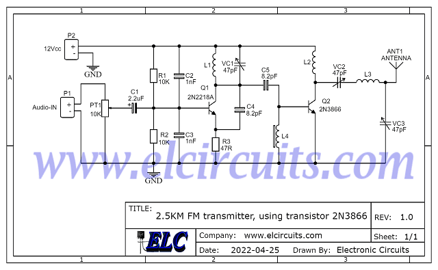
Fig. 2 – Schematic 2.5KM FM transmitter, using transistor 2N3866
🔧 Circuit Adjustments
The transmitter frequency adjustment, is regulated through CV1 trimmer, and CV2 and CV3 trimmers, to regulate the antenna impedance matching, must be done with patience for a better use.
The coil L1, L2 and L3 must be made with enameled wire 22 AWG of 1 cm in diameter with air core, number of turns is described in the component list.
L4 is a 10uH RF shock, and you could be building your own RF shock by winding 15 turns of thin enamel wire around a 1MΩ resistor, soldering to both ends of the copper wire, at each end of the resistor.
The antenna can be a length of rigid wire between 20 and 50 cm for short ranges, or use a 1/2 wave dipole antenna for long ranges.
You might also be interested in:
- FM Transmitter 70MHz to 150MHz using MAX2606 IC with PCB
- FM Transmitter 75 to 108MHz using BA1404 IC with PCB
⚡ The Power Supply
The power source can be from 12Vdc to 16Vdc, if a power supply is used, well filtered sources must be used, due to the sensitivity of the circuit.
Don’t use large wires, always use short wires, and shield the transmitter circuit source. The current consumed by the circuit is around 120mA when powered by 12V, and 400mA when powered by 16V.
🧮 Components List
- Semiconductors
- Q1 …………. 2N2218 or 2N2219 NPN transistor
- Q2 ………….. 2N3866 or 2N4427 NPN Transistor
- Resistors
- R1, R2 ……. 10KΩ 1/4W Resistor (brown, black, orange, gold)
- R3 …………. 47Ω 1/4W Resistor (yellow, violet, black, gold)
- PT1 ……….. 10KΩ Potentiometer
- Capacitors
- C1 …………. 2.2uF /16V Electrolytic Capacitor
- C2, C3 ……. 1nF Ceramic/Polyester Capacitor
- C4, C5 ……. 8.2pF Ceramic Capacitor
- VC1, 2, 3 … 0 ~ 47pF Trimmers
- Coils
- L1 …………… 4 Turns, 7mm diameter Inductor
- L2 …………… 3 Turns, 7mm diameter Inductor
- L3 …………… 5 Turns, 7mm diameter Inductor
- L4 …………… RFC – 10uH Inductor *See Text
- Miscellaneous
- P1, P2 …. Screw Terminal Type 5mm 2-Pin Connector
- Other ……………………… PCB, Wires, Speaker, etc.
🖨️ PCB – Printed Circuit Board
In Figure 3, we provide PCB – Printed Circuit Board, in GERBER, PDF and PNG files. These files are available for free download, on the MEGA server, in a direct link, without any bypass.
All to make it easier for you to do a more optimized assembly, either at home, or with a company that prints the board. You can download the files in the Download option below.
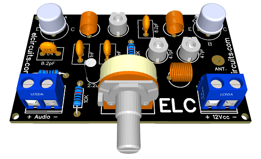
Fig. 3 – PCB – 2.5KM FM transmitter, using transistor 2N3866
📥 Files to download, Direct Link:
Click on the link beside: GERBER, PDF and PNG files
✨ Our Gratitude and Next Steps
We sincerely hope this guide has been useful and enriching for your projects! Thank you for dedicating your time to this content.
Your Feedback is Invaluable:
Have any questions, suggestions, or corrections? Feel free to share them in the comments below! Your contribution helps us refine this content for the entire ElCircuits community.
If you found this guide helpful, spread the knowledge!
🔗 Share This Guide
Best regards,
The ElCircuits Team ⚡


