 Português
 Español
FM Transmitter 75-108 MHz with BA1404 IC + PCB: Build Your Own
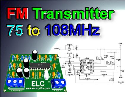
Fig. FM Transmitter 75 to 108MHz using BA1404 IC with PCB
Build Your Own FM Transmitter: Step-by-Step Guide with BA1404 IC & PCB
This is a Stereo FM Transmitter, based on BA1404 Hi-Fi Integrated Circuit, which is a stereo FM modulator that creates composite stereo signals, with low consumption, maximum 3mA, and an operating voltage between 1.5 to 2V.
The FM modulator has carriers in FM transmission band (75~108MHz). It develops signals composed of a MAIN signal (L+R), a SUB signal (L-R) and a pilot signal (19KHz) using 38KHz crystal oscillators.
🛠️ Feature
- Available in DIP18 and SOP18 packages
- Low operating voltage range (1.0V ~ 2V)
- Low power consumption, typically 3mA
- Requires few external components
🧷 Applications
- FM stereo Transmitters
- Wireless Microphones
- FM PLL Oscillator
⚠️ ATTENTION! ⚠️
For each Country, Region, State… There are Laws on broadcasting, telecommunications, audio and video transmission, etc.
Do not use telecommunications equipment without authorization from the entities responsible for transmitting Radio Frequencies.
Electronic Circuits teaches electronics applied to various segments, with the aim of improving knowledge, we do not support or take responsibility for any type of illegal operation.
For any operation with RF, we recommend looking for the competent regulatory agencies, seeking certification and/or legalization.
You might also be interested in:
- FM Transmitter 70MHz to 150MHz using MAX2606 IC with PCB
- 2.5KM FM transmitter, using transistor 2N3866 with PCB
🔌 The transmitter circuit
The schematic diagram of the FM Transmitter 75 to 108MHz using BA1404 IC, is shown in Figure 2 below, it is a simple circuit to assemble, there are few external components to solder, however it is a circuit of great quality and stability.

Fig. 2 – Diagram Schematic FM Transmitter 75 to 108MHz using BA1404 IC
🌀 The Coil
The L1 coil is a Model 750A3.5T Inductor, however, you can make your own inductor by winding 3 to 4 turns of 24 AWG copper wire, or 0.5 mm diameter copper wire, into a 5 mm diameter ferrite core.
📶 The Antenna
The antenna can be used with a telescopic antenna purchased at electronics stores, if you don’t have it, you can use approximately 30cm of rigid wire, which will work perfectly.
🧮 Component List
- Semiconductors
- CI1 …… BA1404 Integrated Circuit
- Resistors
- R1, R2 …. 47KΩ resistor (yellow, violet, orange, gold)
- R3 ……….. 270Ω resistor (red, violet, brown, gold)
- R4 ……….. 150KΩ resistor (brown, yellow, green, gold)
- R5 ……….. 5.6KΩ resistor (green, blue, red, gold)
- R6, R7 …. 27KΩ resistor (red, violet, orange, gold)
- Capacitors
- C1, C2, C6, C12, C13 .. 1nF Ceramic Capacitor
- C3, C4, C5, C14 ………. 10uF 16V Electrolytic Capacitor
- C7, C10 ………………….. 10pF Ceramic Capacitor
- C8, C9, C11 …………….. 15pF Ceramic Capacitor
- C15 ………………………… 220pF Ceramic Capacitor
- Inductor
- L1 ……… 750A3.5T Inductor *see text
- Crystal
- CR1 …… 38KHz Crystal
- Miscellaneous
- P1, P2 …. Screw Terminal Type 5mm 2-Pin Connector
- ANT1 …. Telescopic Antenna *See Text
- Others …. Printed Circuit Board, tin, wires, etc.
🖨️ The PCB – Files to Download
In Figure 3, we provide the PCB – Printed Circuit Board, in GERBER, PDF and PNG files. These files are available for free download, on the MEGA server, in a direct link, without any bypass.
All to make it easier for you to do a more optimized assembly, either at home, or with a company that prints the board. You can download the files in the Download option below.
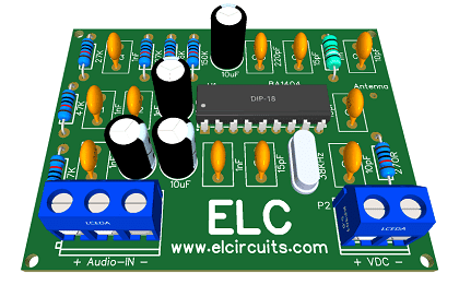
Fig.3 – PCB FM Transmitter 75 to 108MHz using BA1404 IC
📥Files to download, Direct Link:
Click on the link beside: GERBER, PDF and PNG files
✨ Our Gratitude and Next Steps
We sincerely hope this guide has been useful and enriching for your projects! Thank you for dedicating your time to this content.
Your Feedback is Invaluable:
Have any questions, suggestions, or corrections? Feel free to share them in the comments below! Your contribution helps us refine this content for the entire ElCircuits community.
If you found this guide helpful, spread the knowledge!
🔗 Share This Guide
Best regards,
The ElCircuits Team ⚡


