 Português
 Español
How to Wire the Neutrik NCJ6FI-S Combo Jack (XLR / TRS Diagram)
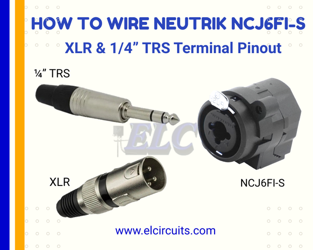
Schematic Wiring of Combined Female XLR / 1/4″ Neutrik NCJ6FI-S
Hello, electronics enthusiasts!
Today we’re going to dive deep into the world of professional audio connectors with a definitive guide on the Neutrik NCJ6FI-S Combined Female XLR/1/4″ Plug. If you work with sound systems, build equipment, or are simply an audio enthusiast, this article will solve all your doubts about this essential component.
First of all, I need to clarify a crucial point that many professionals still have doubts about: this NCJ6FI-S combined connector is specially designed for “snake” type audio panels – those you see on the sides of mixing consoles or in professional racks, with multiple inputs strategically organized.
🔍 Why the NCJ6FI-S is Gold for Audio Panels (Snakes)?
The snake (or breakout box) is a fundamental component in any professional audio system, serving as a central hub for connections between microphones, instruments, and the mixing console. The Neutrik NCJ6FI-S connector has become the gold standard for these applications for three main reasons:
- Space saving – In an audio panel where every centimeter counts, having a single connector that accepts both XLR and 1/4″ is revolutionary
- Operational flexibility – Allows the sound technician to connect any type of source without needing adapters
- Signal integrity – Designed to maintain the quality of balanced audio even with mixed connections.
🔌 Pin Layout in the Neutrik Female Plug: Understanding the Connector’s DNA
Let’s unravel together the internal architecture of this little giant. There are 4 main models in Neutrik’s line of combined connectors, but what interests us today, and the most used in professional audio panels, is the NCJ6FI-S with its 7 contact pins intelligently distributed.
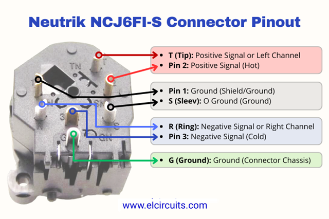
Fig. 2 – Pinout of XLR/1/4″ Neutrik Connector
What makes this connector so special is how it manages two different connection protocols in a single body: the 3-pin XLR (for balanced signals) and the 3-section 1/4″ TRS (for stereo or balanced mono). It’s like having two connectors in one, without losing quality!
Fig. 3 – Schematic Diagram of Neutrik NCJ6FI-S Neutrik
Practical analogy: Think of the NCJ6FI-S as an “audio international airport”. Just as an airport receives flights from different airlines in connected terminals, this connector receives signals from different formats (XLR and 1/4″) in a single “terminal”, allowing them to share the same infrastructure without interference.
“TRS” – When You Need Direct Instrument Connection
Let’s start with the most common scenario in studios and stages: direct connection of instruments like guitars, basses, and keyboards. When you’re using only the 1/4″ TRS connector, the connections follow a specific pattern that ensures signal integrity.
The secret lies in the three contact points of the 1/4″:
- T (Tip) – The positive signal or left channel
- R (Ring) – The negative signal or right channel
- S (Sleeve) – The ground
In the diagram below (Figure 4), you’ll see exactly how to make the connection when using only the 1/4″ connector in your audio snake or audio panel project.

Fig. 4 – Schematic wiring of Neutrik NCJ6FI-S connector for TRS input connector
Pro tip for designers: When building your snake for instruments, use cables with double shielding for TRS connections. The NCJ6FI-S has excellent noise rejection, but good cable shielding perfectly complements its characteristics, eliminating that annoying hum during recordings!
“XLR” – For Microphones and Professional Balanced Signals
Now, when you’re working with microphones or any other signal that needs a balanced connection, the XLR side of the connector comes into play. The XLR standard is the heart of professional audio systems, and understanding its pinout is fundamental.
On the XLR connector:
- Pin 1 – Ground (Shield/Ground)
- Pin 2 – Positive signal (Hot)
- Pin 3 – Negative signal (Cold)
This pinout pattern is crucial for noise rejection over long distances – an essential feature in any professional audio panel. The diagram below (Figure 5) shows exactly how to make the connection when using only the XLR connector in your project.
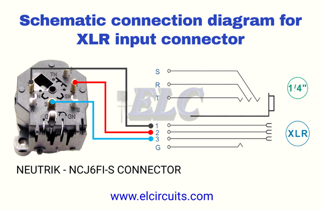
Fig. 5 – Schematic Wiring of Neutrik NCJ6FI-S for XLR Input Connector
Here’s a detail that many experienced technicians still get confused about: the XLR standard for microphones is different from the XLR standard for speakers. In the case of the NCJ6FI-S, we’re specifically talking about the standard for microphones (3-pin XLR), where pin 2 is “hot” and pin 3 is “cold”.
🔍 Did You Know?
The current XLR pinout standard (Pin 2 = Hot) was established by the AES (Audio Engineering Society) in the AES14-1992 standard. Before that, some manufacturers used the inverted standard (Pin 3 = Hot), which caused a lot of confusion. Fortunately, today we have a universal standard thanks to this standard!
⚡ Combined Connection: The Real Power of the NCJ6FI-S in Audio Panels
Now we come to the heart of our article: how to configure the connector to work with both types of connection simultaneously – which makes it the perfect component for snakes and professional audio panels.
The magic happens through a simple connection between the corresponding pins, creating a circuit that allows the signal to flow correctly regardless of the type of connector you’re using. It’s like having an “automatic switch” inside the connector!

Fig. 6 – Schematic wiring of Neutrik NCJ6FI-S for combined XLR/TRS connector
The combined connection follows these simple but fundamental rules:
- XLR Pin 1 connected to TRS Pin S (Ground)
- XLR Pin 2 connected to TRS Pin T (Positive signal)
- XLR Pin 3 connected to TRS Pin R (Negative signal)
This intelligent configuration is what allows you to connect an XLR microphone to a connector that also accepts 1/4″, without needing manual switches or additional configurations. It’s pure audio engineering in action!
“Mono” – Configuration for 1/4″ TS (Mono) Connector
For applications that require only mono signal (like most musical instruments), you can simplify the connection using only two of the three contacts of the 1/4″. This is the classic “TS” (Tip-Sleeve) configuration that you find in guitars and basses.

Fig. 7 – Wiring diagram of Neutrik NCJ6FI-S connector and TS – 1/4″ connector
In this configuration:
- T (Tip) – Audio signal
- S (Sleeve) – Ground
- R (Ring) – Not connected (or connected to ground for better noise rejection)
⚙️ Technical Features That Make the NCJ6FI-S a Gold Standard in Professional Audio
Now that you already understand the logic behind the connections, let’s dive into the technical specifications that make the Neutrik NCJ6FI-S the most reliable combined connector on the market. Don’t worry – I’ll explain each feature in a practical way, relating it to its real use in the day-to-day of professional audio.
🔧 Ultra-Low Contact Resistance: The Secret to Clean Signal
With contact resistance below 10 mΩ on the XLR and 20 mΩ on the 1/4″, the NCJ6FI-S ensures that practically no signal is lost in the connection. This means that subtle detail in the vocalist’s voice or the rich harmonic of the guitar arrives intact at the mixing console – without loss of quality or introduction of noise.
Practical tip: In large PA systems, where signals travel long distances, this low resistance is critical to avoid signal degradation. It’s like having a perfectly smooth road for your audio signal to travel!
🛡️ Industrial Durability: Designed to Survive the Most Intense Shows
When you’re working at professional events, you can’t risk a connector failing in the middle of the show. The NCJ6FI-S was designed to withstand more than 1,000 connection/disconnection cycles without loss of quality – which means you can assemble and disassemble your system hundreds of times without worrying.
⚡ Specifications That Really Matter for Your Snake Project
Let’s translate those technical tables provided by the manufacturer into clear and real parameters for your project. It’s not enough to know the numbers – you need to understand how they impact your daily work:
🔌 Rated Current: 7.5A (XLR and 1/4″)
This specification means that the connector can handle high-power signals without overheating or degrading. For context: a typical microphone signal operates around 0.001A. This gives an impressive safety margin of 7,500 times above what’s needed!
⚠️ Beware of imitations: Generic connectors often have rated current below 1A, which can cause signal loss or even damage in high-power systems.
📏 Panel Thickness: Maximum 7mm
This specification is crucial when you’re designing your snake or audio panel. The NCJ6FI-S was designed to fit perfectly in standard panels from 1.5mm to 7mm thick – the most common range in professional racks.
Pro tip for manufacturing: When designing your mounting board, leave a 0.5mm clearance around the connector to facilitate installation and avoid mechanical stresses.
🌡️ Temperature Range: -30°C to +80°C
This is one of the features that makes the NCJ6FI-S ideal for professional use in any weather condition. Whether in an air-conditioned studio or at an outdoor festival in the summer, the connector maintains its performance.
“I’ve used these connectors in shows in Alaska (-20°C) and in the Arizona desert (+45°C) without any performance problems.” – Testimony from a professional sound technician
🔗 Related Projects That May Be of Interest
🤔 Dúvidas Frequentes (FAQ)
❓Frequently Asked Questions About: Neutrik NCJ6FI-S (XLR/1/4″) Connector – FAQ
1. What is the Neutrik NCJ6FI-S connector?🔽
It’s a combined receptacle that unites in a single body the female XLR and 1/4″ (TRS/TS) connectors, allowing greater versatility in mixing consoles, audio equipment, and musical instruments.
2. What’s the difference between XLR and 1/4″ connections on the NCJ6FI-S?🔽
XLR (Canon): Used mainly for microphones and balanced signals. 1/4″ TRS: Used for stereo or balanced connections. 1/4″ TS: Used in mono signals, like guitars and basses.
3. How many pins does the connector have and how are they distributed?🔽
The NCJ6FI-S model has 7 contact pins, being: 4 pins dedicated to the XLR input. 3 pins dedicated to the TRS/TS (1/4″) connector.
4. Is it possible to use the XLR and TRS inputs at the same time?🔽
Yes. The combined connector allows parallel connection of XLR and TRS, just make the jumps between the corresponding pins (1 with S, 2 with T, 3 with R), as shown in the manufacturer’s schematic diagram.
5. What are the main electrical characteristics of the NCJ6FI-S?🔽
Contact resistance: < 10 mΩ (XLR), < 20 mΩ (1/4″). Rated current: up to 7.5 A per contact. Rated voltage: up to 50 V. Insulation resistance: > 10 GΩ. Dielectric withstand: 1.5 kVdc.
6. What are the advantages of using the NCJ6FI-S in audio projects?🔽
The main advantages are: Space saving: A single connector replaces two. Versatility: Accepts XLR, TRS and TS. Durability: More than 1000 insertion/removal cycles. Robust construction: Made with high-quality materials from Neutrik.
7. What’s the difference between the NCJ6FI-S and the NCJ6FI-M?🔽
Detailed comparison: This is a question that causes a lot of confusion! Both are combined XLR/1/4″ connectors from Neutrik, but they have different applications:
Feature | NCJ6FI-S | NCJ6FI-M Mounting Type | Panel mounting (front) | PCB mounting (circuit board) Main Application | Audio panels (snakes) | Internal electronic equipment Fastening | Front screws | Board soldering Mechanical Resistance | High (for external use) | Moderate (for internal use)✅ Teacher’s tip: For snakes and professional audio panels, always choose the NCJ6FI-S. The “S” means “Socket” (socket for panel), while the “M” means “Module” (module for PCB).
💡 Professional Tips to Maximize Your NCJ6FI-S
After years of working with these connectors, I want to share some tips I’ve learned in practice – those that aren’t in the manual, but make all the difference:
🔧 Perfect Soldering Technique for Impeccable Connections
Most problems with connectors come from inadequate soldering. Follow this professional process:
- Prepare the wires: Strip 5mm of insulation and “twist” the strands
- Pre-heat the pin: Apply solder to the tip of the iron, then touch the pin for 2 seconds
- Quick soldering: Touch the wire to the heated pin and apply solder – it should take less than 3 seconds
- Visual inspection: The solder should form a smooth cone, not a ball
“A well-soldered connector should look like a perfect drop of water – not too little, not too much. It’s the key to noise-free connections!” – Mixing console maintenance technician.
“Excellence in audio is in the details that most ignore. A quality connector is not a cost – it’s an investment in the clarity of your sound.” – Prof. Audio.
🚀 Conclusion: Transforming Knowledge into Audio Excellence
We’ve reached the end of this definitive guide on the Neutrik NCJ6FI-S, but in reality, it’s just the beginning of your journey to master the art of professional audio panels. Remember that the quality of your system starts with the quality of the connections – and now you have all the necessary knowledge to create impeccable snakes.
💡 Summary of Key Points You Can’t Forget
- The NCJ6FI-S is Gold for snakes: Saves space, offers flexibility and maintains signal integrity
- Combined connection is simple: Just connect XLR Pin 1 to TRS S, Pin 2 to T, and Pin 3 to R
- Authenticity is crucial: Counterfeit connectors are the cause of 70% of noise problems in audio systems
- Perfect soldering makes a difference: Maximum contact time of 3 seconds and quality solder are non-negotiable
- Planning is everything: Always leave 10-20% of extra connectors for future expansion
“A quality connector is not a cost – it’s an investment in the clarity of your sound.” – Prof. Audio
Now that you master all the secrets of the NCJ6FI-S, you’re prepared to elevate your audio projects to a new professional level. It doesn’t matter if you’re an experienced technician, a beginner designer, or an audio enthusiast – this knowledge will make all the difference in the quality of your work.
Original article published on FVML (Portuguese) – july 7, 2019
✨ Our Gratitude and Next Steps
We sincerely hope this guide has been useful and enriching for your projects! Thank you for dedicating your time to this content.
Your Feedback is Invaluable:
Have any questions, suggestions, or corrections? Feel free to share them in the comments below! Your contribution helps us refine this content for the entire ElCircuits community.
If you found this guide helpful, spread the knowledge!
🔗 Share This GuideBest regards,
The ElCircuits Team ⚡

XEvil 5.0 automatically solve most kind of captchas,
Including such type of captchas: ReCaptcha v.2, ReCaptcha-3, Google, Solve Media, BitcoinFaucet, Steam, +12k
+ hCaptcha, FC, ReCaptcha Enterprize now supported in new XEvil 6.0!
+ CloudFlare TurnsTile, GeeTest captcha now supported in new XEvil 7.0!
+ XEvil 7.0 was released! ReCaptcha v2 solving speed increased x2!
+ XEvil can solve captchas from OpenClaw AI bot!
1.) Fast, easy, precisionly
XEvil is the fastest captcha killer in the world. Its has no solving limits, no threads number limits
2.) Several APIs support
XEvil supports more than 6 different, worldwide known API: 2Captcha, anti-captcha (antigate), rucaptcha, DeathByCaptcha, etc.
just send your captcha via HTTP request, as you can send into any of that service – and XEvil will solve your captcha!
So, XEvil is compatible with hundreds of applications for SEO/SMM/password recovery/parsing/posting/clicking/cryptocurrency/etc.
3.) Useful support and manuals
After purchase, you got access to a private tech.support forum, Wiki, Skype/Telegram online support
Developers will train XEvil to your type of captcha for FREE and very fast – just send them examples
4.) How to get free trial use of XEvil full version?
– Try to search in Google “Home of XEvil”
– you will find IPs with opened port 80 of XEvil users (click on any IP to ensure)
– try to send your captcha via 2captcha API ino one of that IPs
– if you got BAD KEY error, just tru another IP
– enjoy! 🙂
– (its not work for hCaptcha!)
WARNING: Free XEvil DEMO does NOT support ReCaptcha, hCaptcha and most other types of captcha!
http://xrumersale.site/
Your comment is awaiting moderation.