Português
 Español
Arduino Lesson 6 – How to Use Analog Output to Fade an LED

Arduino: Lesson 6 – How to use analog output to fade an LED
Welcome to Lesson 6 – Basic Arduino Course
In today’s lesson, we will learn how to use an analog output to increase and decrease the brightness of a LED. In this example, we will use the analogWrite() function, which triggers a PWM wave on an Arduino pin.
We will use PWM to vary the brightness of a LED as an example, but nothing prevents us from also using it to drive a motor and control its speed, the concept is the same.
The analogWrite() function triggers a square wave at the specified duty cycle until the next analogWrite() call.
The frequency of the PWM signal is around 490 Hz on most Arduinos, however on Arduino Uno and some similar boards, pins 5 and 6 use a frequency of about 980 Hz.
On most Arduino boards with ATmega168 or ATmega328 chips, this function works on pins 3, 5, 6, 9, 10 and 11. On the Arduino Mega this function works on pins 2 to 13 and 44 to 46.
Hardware Required
- Arduino Board
- LED
- 200 ohms resistor
- Jumper Wires
- Protoboard (optional)
The Circuit
The circuit is quite simple, we connect a LED in series with a 220 ohm resistor used to limit the current in the LED as we learned in the previous lessons, and we connect the PWM 9 port of the Arduino UNO as shown in Figure 2 below.
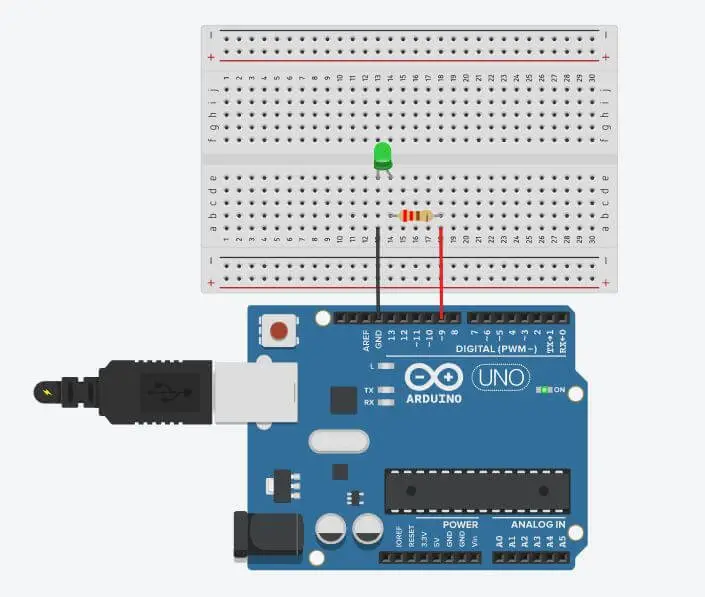
Fig. 2 – Using an analog output to fade an LED – tinkercad.com
We use a Protoboard to facilitate the connections, but you can also connect the wires directly to the Arduino.
The Code
The analogWrite() function writes an analog value to the Arduino pin. It is important to remember that this output is not a pure analog output that we can use to generate a pure sine wave, but this output is a PWM wave control.
When we execute the call to the analogWrite() function, the pin will generate a constant square wave with the specified duty cycle until the next function call.
After building the circuit, connect your Arduino board to your computer, launch Arduino Software (IDE), copy the code below and paste it into your Arduino IDE. But first let us understand the code line by line.
- In Line 3, we declared ledPin to digital Pin 9 where we connect the LED to the digital Pin 9.
- In Line 5, we enter the void setup() function. This function is read only once when the Arduino is started.
- In Line 6, we define Port 9 as the output, using the pinMode(); function;
01 02 03 04 05 06 07 08 09 | //Arduino: Lesson 6 – How to use Analog Output to fade an LED int ledPin = 9; // LED connected to digital pin 9 void setup() { // This function is called once when the program starts pinMode(ledPin, OUTPUT); // Set the digital pin as output: } //———————- www.elcircuits.com —————————– |
- In Line 09, we enter in the loop() function does precisely what its name suggests, and loops consecutively.
- In Line 11, the control structure For, is used to repeat a block of statements enclosed in curly braces. An increment counter is usually used to increment and terminate the loop.
- In Line 12, we run the analogWrite() function, this function writes an analog value (PWM wave) to pin 9, in this case we are increasing the PWM value from 5 to 5, to increase the LED brightness up to the maximum value of 255.
- In Line 13, we use the function delay(); to wait for 30 milliseconds to see the dimming effect.
1 … 09 10 11 12 13 14 15 16 | // Arduino: Lesson 6 – How to use Analog Output to fade an LED void loop() { // The loop function runs over and over again forever for (int fadeValue = 0; fadeValue <= 255; fadeValue += 5 { // fade in from min to max in increments of 5 points: analogWrite(ledPin, fadeValue); // sets the value (range from 0 to 255) delay(30); // wait for 30 milliseconds to see the dimming effect } //————————– www.elcircuits.com ———————————- |
- In Line 16, the control structure For, is used to repeat a block of statements enclosed in curly braces. An increment counter is usually used to increment and terminate the loop.
- In Line 17, we run the analogWrite() function, this function writes an analog value (PWM wave) to pin 9, in this case, we are decreasing the PWM value from 5 to 5, to decrease the LED brightness to the minimum value of 0.
- In Line 18, we use the function delay(); to wait for 30 milliseconds to see the dimming effect.
1 … 16 17 18 19 20 21 22 | // Arduino: Lesson 6 – How to use Analog Output to fade an LED for (int fadeValue = 255; fadeValue >= 0; fadeValue -=5){ //fade out from max to min in increments of 5 points analogWrite(ledPin, fadeValue); // sets the value (range from 255 to 0) delay(30); // wait for 30 milliseconds to see the dimming effect } } //———————– www.elcircuits.com —————————— |
The complete code is showed in the sketch below!
1 2 3 4 5 6 7 8 9 10 11 12 13 14 15 16 17 18 19 20 21 22 23 | // Arduino: Lesson 6 – How to use Analog Output to fade an LED int ledPin = 9; // LED connected to digital pin 9 void setup() { // This function is called once when program starts pinMode(ledPin, OUTPUT); // Set the digital pin as output: } void loop() { // The loop function runs over and over again forever for (int fadeValue = 0 ; fadeValue <= 255; fadeValue += 5) { // fade in from min to max in increments of 5 points: analogWrite(ledPin, fadeValue); // sets the value (range from 0 to 255) delay(30); // wait for 30 milliseconds to see the dimming effect } for (int fadeValue = 255 ; fadeValue >= 0; fadeValue -= 5) { // fade out from max to min in increments of 5 points: analogWrite(ledPin, fadeValue); // sets the value (range from 0 to 255) delay(30); // wait for 30 milliseconds to see the dimming effect } } //—————— www.elcircuits.com ———————– |
Next Lesson
Previous Lesson
✨ Our Gratitude and Next Steps
We sincerely hope this guide has been useful and enriching for your
projects! Thank you for dedicating your time to this content.
Your Feedback is Invaluable:
Have any questions, suggestions, or corrections? Feel free to share them
in the comments below! Your contribution helps us refine this
content for the entire ElCircuits community.
If you found this guide helpful, spread the knowledge!
Best regards,
The ElCircuits Team ⚡