 Português
 Español
Understanding Electromagnetic Relays – Characteristics & Applications

Electromagnetic Relays: Types, Operation, Characteristics and Applications!
Electromagnetic Relays: Understanding Operation and Practical Applications
Hello Everyone!
Have you ever imagined how a simple component the size of a coin can control industrial motors or entire electrical systems? That’s exactly what electromagnetic relays do. They are the “bridge” between weak signals and high-power circuits, essential in home automation, industrial machines, and even household appliances..
In today’s post, we’ll explore in detail the operation, characteristics, and practical applications of electromagnetic relays.
🔍 Why are Relays so Important?
Electromagnetic relays are fundamental components in electronics and automation, functioning as electrically controlled switches. They allow a low-power circuit to control a high-power circuit safely and in isolation, being essential in numerous applications, from simple hobby projects to complex industrial systems.
🤔 What is an Electromagnetic Relay?
An electromagnetic relay is an electromechanical device that uses voltage, converts it into electromagnetic force, forming a magnetic field to control the switching of electrical contacts. It is composed of a small coil, a movable armature with spring, and switching contacts.
When a current flows through the coil, the electromagnet is activated, attracting the movable armature and switching the contacts. This allows a low-power signal to control a high-power circuit.
💡 Analogy for Better Understanding
Think of a relay as a light switch controlled by a magnet. When you turn on the switch (energize the coil), the magnet attracts a lever (armature) that closes or opens another electrical circuit. This allows you to control a high-power lamp using only a small low-power switch!
ℹ️ Main Types of Relays
There are several types of relays, each designed to meet specific needs. The main types include:
| Relay Type | Characteristics | Typical Applications |
|---|---|---|
| Electromagnetic | Uses coil and contact system | Motor control, home automation |
| Solid State (SSR) | No moving parts, uses semiconductors | Temperature control, LED lighting |
| Thermal | Monitors temperature, uses bimetallic strip | Overload protection, climate control |
| Time | Controls operation time | Soft motor starting, irrigation |
1. Electromagnetic Relay
- Characteristics: The most common, use a coil and a contact system to control current flow.
- Operation: Uses a coil to generate magnetic field and move contacts.
- Applications:
- Switching in electronic circuits, power supplies, switches.
- Control of electric motors
- Home automation systems (e.g., smart lighting)
- Industrial safety circuits
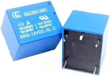
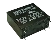
Fig. 2 – Example of Industrial Electromagnetic Relay
2. Solid State Relay (SSR)
- Characteristics: No moving parts, use semiconductor components to control current flow.
- Advantages: No moving parts, longer lifespan and silent operation.
- Applications:
- Load driving circuits
- Temperature control in industrial furnaces
- High-frequency LED lighting
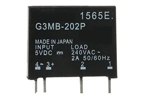
Fig. 3 – Example of Solid State Relay
🌟 Advantages of Solid State Relays
- Silent operation (no mechanical clicks)
- High switching speed
- Less wear (no moving parts)
- Galvanic isolation between input and output
- Resistant to vibrations and mechanical shocks
3. Thermal Relay
- Characteristics: Monitor temperature and disconnect the circuit when overheating occurs.
- How it works: Uses a bimetallic strip that deforms with heat.
- Applications:
- Overload protection in electric motors
- Climate control systems
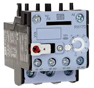
Fig. 4 – Example of a Thermal Relay
4. Time Relay
- Characteristics: Allow control of the operation time of electrical circuits.
- Functionality: Adds programmable delays to switching.
- Applications:
- Soft motor starting
- Automatic irrigation systems
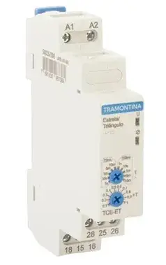
Fig. 5 – Example of a Time Relay
⏱️ Types of Time Relays
Time relays can be classified as:
- On energization: start counting when they receive power
- On de-energization: start counting when power is cut off
- Cyclic: automatically alternate between on/off states
- Star-delta: specific for starting three-phase motors
👨🔧 Operation of the Electromagnetic Relay (Our Focus)
The operation of an electromagnetic relay can be understood by analyzing its internal structure, as illustrated in Figure 6 below. The electromagnetic coil is the heart of the relay, responsible for generating the magnetic field that switches the contacts.
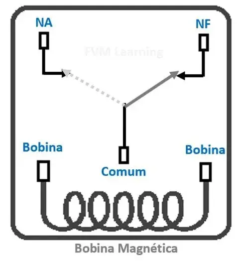
Fig. 6 – Schematic diagram of an electromagnetic relay
- 1️⃣ Coil Energization: When a current flows through the coil, a magnetic field is generated.
- 2️⃣ Contact Switching: The magnetic field attracts the movable armature, switching the contacts from NC (Normally Closed) to NO (Normally Open).
- 3️⃣ De-energization: When the current in the coil ceases, the movable armature returns to its original position due to the spring force, switching the contacts back to NC.
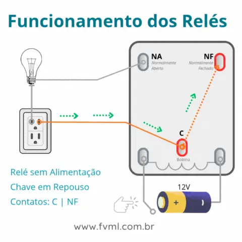
Fig. 7 – Operation of the Electromagnetic Relay in Practice
🛠️ Characteristics and Architecture of an Electromagnetic Relay – Standard 5-Pin Model
In Figure 8 below, we present a 5-pin electromagnetic relay, which will serve as a reference to exemplify its internal architecture. This type of relay is widely used, being considered a standard model for its simplicity, availability in the market and ease of understanding.
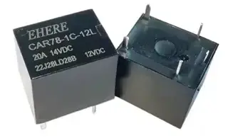
Fig. 8 – Characteristics and Architecture of an Electromagnetic Relay – Standard 5-Pin Relay
In general, most electromagnetic relays available today are composed of five fundamental elements, which work in conjunction to perform electrical switching. They are:
1. Electromagnetic Coil
- Responsible for generating the magnetic field when energized.
2. Movable Armature
- Moving part that switches the contacts when attracted by the magnetic field.
3. Switching Contacts
- NC (Normally Closed), NO (Normally Open) and COM (Common).
4. Magnetic Core
- Improves the efficiency of the magnetic field.
5. Return Mechanism
- Usually a spring that returns the armature to the original position.
These components form the functional core of the relay, enabling the actuation of electrical circuits safely and in isolation, as illustrated in Figure 9 below.
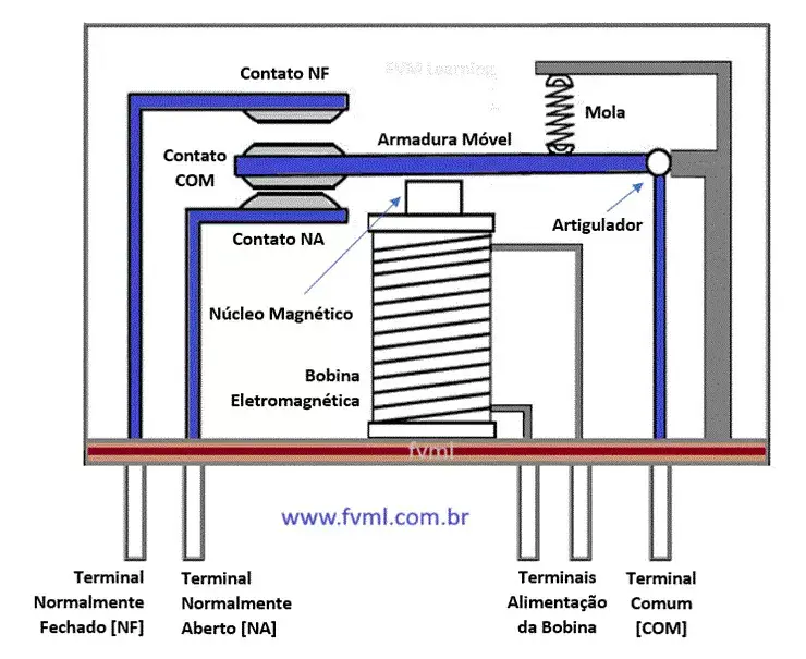
Fig. 9 – Internal architecture of an Electromagnetic Relay – Standard 5-Pin Relay
🧲 Configuration of the Electromagnetic Relay
Electromagnetic relays can have different configurations, and named with designations such as:
➡️ SPST (Single Pole Single Throw)
The SPST relay has a total of four terminals. Of these two terminals can be connected or disconnected. The other two terminals are necessary for the coil to be connected.

➡️ SPDT (Single Pole Double Throw)
The SPDT relay has a total of five terminals. Of these two are the coil terminals. A common terminal is also included, which connects to any of the other two.

➡️ DPST (Double Pole Single Throw)
The DPST relay has a total of six terminals. These terminals are divided into two pairs. Thus, they can act as two SPST, actuated by a single coil. Of the six terminals, two of them are coil terminals.
➡️ DPDT (Double Pole Double Throw)
The DPDT relay is the largest of all. It mainly has eight relay terminals. Of these two rows are designed to be switched by terminals. They are designed to act as two SPDT relays that are actuated by a single coil.

Each configuration offers different switching possibilities.
| Configuration | Number of Terminals | Controlled Circuits | Typical Application |
|---|---|---|---|
| SPST | 4 | 1 simple circuit | Simple on/off switching |
| SPDT | 5 | 1 circuit with 2 options | Selection between two sources |
| DPST | 6 | 2 independent circuits | Simultaneous control of 2 circuits |
| DPDT | 8 | 2 circuits with 2 options each | Polarity reversal, complex selection |
🔗 Related Content
If you liked this project, you might also be interested in these other articles:
If you liked this project, you might also be interested in these other articles:
🧱 Applications of Relays
Relays are widely used in various applications:
⚙️ Motor Control
To turn on and off electric motors in industrial and residential systems.
🛡️ Circuit Protection
Overload relays protect motors and circuits against overloads.
🏭 Industrial Automation
In industrial control systems for process automation.
🚨 Alarm and Security Systems
For control of alarms and residential and industrial security systems.
🔧 Practical Examples in Daily Life
- Automotive: Relays control headlights, horns and fuel pumps
- Residential: Thermostats and automated lighting systems
- Appliances: Microwaves, washing machines and refrigerators
- Telecommunications: Switching in telephone and network systems
💡 How to Choose the Ideal Relay: Essential Tips for Safe and Efficient Selection
The correct choice of a electrical relay is fundamental to ensure safety, durability and performance in your automation or control system. See the main factors to consider when selecting a relay:
1. Contact and Coil Protection
Contact protection
Minimizes wear caused by electrical arcs, especially in circuits with inductive loads.
Coil protection
Avoids voltage surges during switching, extending the life of the relay and protecting the circuit components.
2. Certifications and Technical Compliance
Opt for relays that have recognized regulatory approvals (such as UL, CE and IEC), ensuring compliance with electrical safety standards and reliability.
3. Switching Time
For applications that require speed, such as protection systems, choose high-speed relays, which offer optimized response times.
4. Electrical Ratings
Current
Relays range from low current models to industrial relays up to 3,000 A.
Voltage
Options range from 300 V AC to 600 V AC, and can reach 15,000 V in specific high-voltage models.
| Application | Recommended Relay Type | Key Specifications |
|---|---|---|
| Home automation | Electromagnetic or SSR | 5-10A, 12-24V DC or 110-220V AC |
| Industrial motor control | Industrial electromagnetic | 20-100A, 24-380V AC |
| Thermal protection | Thermal relay | Adjustable for motor current |
| High-frequency circuits | Solid State (SSR) | Low noise, high speed |
✅ Checklist for Selecting the Ideal Relay
- Check the coil voltage
- Confirm the current capacity of the contacts
- Evaluate the load type (resistive/inductive)
- Consider the operating environment
- Check safety certifications
- Evaluate mechanical and electrical life
- Consider the necessary switching time
- Check galvanic isolation
🧾 Conclusion
Electromagnetic relays are versatile and essential devices in many applications. Understanding their operation and characteristics is crucial to use them efficiently. If you are designing a circuit or automation system, relays offer a reliable and effective solution for controlling electrical circuits.
📝 Key Points to Remember
- Electromagnetic relays function as switches controlled by magnetism
- They allow low-power circuits to control high-power circuits
- There are different types of relays for specific applications
- Proper relay selection is fundamental for system safety and efficiency
- Relays continue to be essential components even with the advancement of electronics
❓ Frequently Asked Questions
Find answers to common questions about this amplifier circuit below.
Can I use this amplifier with 4Ω speakers? 🔽
We don’t recommend it. This Bridge configuration was designed to work with a minimum impedance of 8Ω. Using 4Ω speakers can overload the ICs, causing overheating and possible permanent damage.
Is it necessary to use heat sinks on the TDA7294 ICs? 🔽
Yes, absolutely! The TDA7294 ICs dissipate significant heat during operation, especially at high powers. We recommend using adequate heat sinks for each IC, with sufficient area to keep the temperature below 80°C.
Can I convert this amplifier into a stereo system? 🔽
To create a stereo system, you would need to build two circuits identical to this one, one for each channel. Alternatively, you could configure each TDA7294 individually (instead of in bridge) to create two lower power channels.
What is the expected sound quality of this amplifier? 🔽
The TDA7294 is known for its excellent sound quality, with low harmonic distortion (typically less than 0.1%) and low noise. You can expect a clean and detailed sound, suitable for high-fidelity audio applications.
Is this amplifier suitable for guitars or musical instruments? 🔽
Yes, this amplifier works very well for guitars and other musical instruments. Its high power and low distortion provide a clean and dynamic sound. For guitar applications, you may want to add a preamplifier circuit or effects before this power stage.
🚀 Did you like this article? Leave your comment!
Share your experiences with relays or ask your questions in the comments section below. Your participation helps enrich our content!
✨ Our Gratitude and Next Steps
We sincerely hope this guide has been useful and enriching for your projects! Thank you for dedicating your time to this content.
Your Feedback is Invaluable:
Have any questions, suggestions, or corrections? Feel free to share them in the comments below! Your contribution helps us refine this content for the entire ElCircuits community.
If you found this guide helpful, spread the knowledge!
🔗 Share This Guide
Best regards,
The ElCircuits Team ⚡


