 |
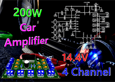
| 14V 4 Channel 200W MOSFET Quad Bridge Power Amplifier using TDA7850 with PCB |
Unleash Power and Sound with a 14V 4-Channel 200W MOSFET Quad Bridge Amplifier using TDA7850 and PCB
This is a 14V 4 Channel 200W MOSFET Quad Bridge Power Amplifier, it uses an TDA7850 Integrated Circuits, in Quad Bridge Mode to drive four power speakers.
The circuit provides a total output power of 200W, and this with good sound quality, powered from a unipolar 14V power supply.
The Amplifier responds very well to all audible frequency ranges, and has a minimalist, compact design, which makes this amplifier a good choice for an unprecedented range of application.
🧷 IC Description
The TDA7850 is a breakthrough MOSFET technology Class AB audio power amplifier in Flexiwatt 25 package designed for high power car radio.
The fully complementary P-Channel / N-Channel output structure allows a rail to rail output voltage swing which, combined with high output current and minimized saturation losses sets new power references in the car-radio field, with unparalleled distortion performances. The TDA7850 integrates a DC offset detector.
You might also be interested in:
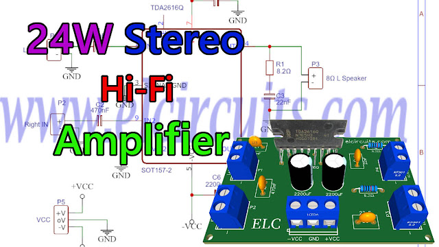
- 24W Stereo Hi-Fi Audio Amplifier using TDA2616 + PCB
- 68W Hi-Fi Audio Power Amplifier using LM3886T IC + PCB
- 4 x 50W High Power Amplifier, 14.4V - IC TDA7563A + PCB
- 320W Power Audio Amplifier, Powered with 14.4V - 2Ω with IC TDA7560 + PCB
- 100W RMS Audio Amplifier IC TDA7294 + PCB
- 200W RMS Stereo Power Amplifier with IC STK4231II + PCB
🧮 IC Features
- High output power capability:
- 4 x 50W / 4Ω max.
- 4 x 30W / 4Ω @ 14.4 V, 1 kHz, 10 %
- 4 x 80W / 2Ω max.
- 4 x 55W / 2Ω @ 14.4V, 1 kHz, 10 %
- MOSFET output power stage
- Excellent 2Ω driving capability
- Hi-Fi class distortion
- Low output noise
- ST-BY function
- Mute function
- Auto mute at min. supply voltage detection
- Low external component count:
- Internally fixed gain (26 dB)
- No external compensation
- No bootstrap capacitors
- On board 0.35 A high side driver
🔌 The Schematic Circuit
In Figure 2 below, we have available the schematic diagram of the 14V 4 Channel 200W MOSFET power amplifier circuit, this circuit is quite simple to assemble.
As we can see there are very few external components, making the circuit very simple to assemble, even for a technician or hobbyist with little experience in electronics can assemble it without much difficulty.
 |
| Fig. 2 - Diagram 14V 4 Channel 200W MOSFET Quad Bridge Power Amplifier using TDA7850 |
It is important to remember to be careful when assembling the circuit, as simple as the circuit is. We must be careful not to invert any components, such as capacitors, or invert the input voltage of the circuit, because the integrated circuit or other components can be damaged easily.
🧮 Components List
- Semiconductors
- U1 ............ TDA7850 Integrated Circuit
- Resistors
- R1 ............ 47KΩ Resistor (yellow, violet, orange, gold)
- R2, R3 ..... 10K resistor (brown, black, orange, gold)
- Capacitors
- C1 to C4 ... 220nF Ceramic/Polyester Capacitor
- C5, C6 ...... 1μF Ceramic/Polyester Capacitor
- C7 ............. 470nF Ceramic/Polyester Capacitor
- C8 ............. 47μF / 25V Electrolytic Capacitor
- C9 ............. 2.200μF / 25V Electrolytic Capacitor
- C10 ........... 100nF Ceramic/Polyester Capacitor
- Miscellaneous
- P1 to P9 .... Screw Terminal Type 5mm 2-Pin Connector
- Other ........ PCB, Wires, Speaker, etc.
⚡ Power Supply
This amplifier is powered by unipolar source, with direct current, the maximum current required by the circuit is approximately 15 Amperes.
And you can connect it directly to a car battery, or a motorcycle battery, or a no-break battery, or a bench power supply...
The power will be according to the power supply, and as already shown in the IC features above, to have 4 outputs of 50W we have to supply the circuit with 14.4V.
🖨️ Printed Circuit Board
In Figure 3, we provide the PCB - Printed Circuit Board, in GERBER, PDF and PNG files. These files are available for free download, on the MEGA server, in a direct link, without any bypass.
All to make it easier for you to do a more optimized assembly, either at home, or with a company that prints the board. You can download the files in the Download option below.
 |
| Fig. 3 - PCB 14V 4 Channel 200W MOSFET Quad Bridge Power Amplifier using TDA7850 |
📥 Files to Download, Direct Link:
👋 I hope you enjoyed it!!!
If you have any questions, suggestions or corrections, please leave them in the comments and we will answer them soon.
🙏 Subscribe to our blog!!! Click here - elcircuits.com!!!
My Best Regards!!!
If you have any questions, suggestions or corrections, please leave them in the comments and we will answer them soon.
🙏 Subscribe to our blog!!! Click here - elcircuits.com!!!
My Best Regards!!!