 Português
 Español
5W Stereo Audio Amplifier Circuit using TEA2025 IC + PCB
5W Stereo Audio Amplifier Circuit using TEA2025
In this article, we show you how to build a simple and portable 5W stereo audio amplifier using the TEA 2025 Integrated Circuit.
This circuit built based on TEA2025 IC which is a monolithic integrated audio amplifier in a 16-pin plastic dual in line package manufactured by UTC.
The circuit has Internal Thermal Protector. It is designed for portable cassette players, mp3 players and radios.
You can also use it as your smartphone or PC audio amplifier. This circuit requires 9V power supply to work, you may use a power supply circuit with output 9V 500mA DC current or a 9V lead acid battery.
Features
- The power supply voltage range is from 3V to 15V.
- Working Voltage down to 3V
- Few External components
- Dual or Bridge Connection Modes
- High Channel isolation
- Very low switch On/Off Noise
- Voltage gain up to 45dB (Adjustable with external resistor)
- Soft clipping
- Internal Thermal protection
Working Explanation
Input Capacitor
Bootstrap
Power supply
Applications
- Electronic Instruments
- PC sound speaker
- Home theater systems
- Hi-fi electronic gadgets and devices
- Robotics applications
- Children’s gadgets and toys, etc.
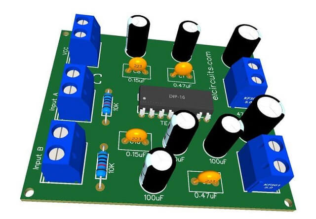
In Figure 1 below, we show the complete 5W Stereo Audio Amplifier Circuit using TEA2025 IC, and that you can download the files in option; Download files below at the bottom of the page.
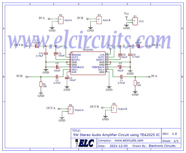
Fig. 2 – Schematic 5W Stereo Audio Amplifier Circuit using TEA2025 IC
Components List
- U1 ………………………….. TEA2025 Integrated circuit
- R1, R2 ……………………. 10K resistor (brown, black, orange, gold)
- C1, C2 ……………………. 0.47uF ceramic, polyester capacitor
- C3, C4, C5, C6, C9 ….. 100uF electrolytic capacitor
- C7, C11 ………………….. 470uF electrolytic capacitor
- C8, C10 ………………….. 0.15uF ceramic, polyester capacitor
- P1, P2, P3, P4, P5 …. Screw Terminal Type 5mm 2-Pin Connector
- Others ……………………. PCB, tin, wires, etc.
PCB – Download
Click on the direct link to download the files: Layout PCB, PDF, GERBER, JPG
✨ Our Gratitude and Next Steps
We sincerely hope this guide has been useful and enriching for your projects! Thank you for dedicating your time to this content.
Your Feedback is Invaluable:
Have any questions, suggestions, or corrections? Feel free to share them in the comments below! Your contribution helps us refine this content for the entire ElCircuits community.
If you found this guide helpful, spread the knowledge!
🔗 Share This Guide
Best regards,
The ElCircuits Team ⚡


