Showing posts with label Electronic Components. Show all posts

Sunday, October 3, 2021

What is a Relay and How it Works?

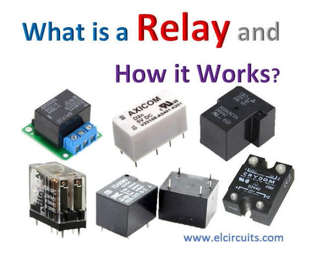
Fig 1. - What is a Relay and How it Works?

What is a relay?

A relay is an electromagnetic switch used to turn a circuit on and off by a low-power electrical signal, or when multiple circuits need to be controlled by a single signal.

We know that most high-end devices for industrial applications require relays for their effective operation.

Relays are simple switches that are electrically and mechanically operated. Relays consist of an electromagnet and a series of contacts. The switching mechanism is carried out with the help of the electromagnet.

There are also other functional principles for their operation. However, they differ depending on the application.

Why use a Relay?

A relay is mainly used where only a low power signal can be used to control a circuit. It is also used when only one signal can be used to control many circuits.

The use of relays began with the invention of the telephone. They played an important role in exchanging calls in telephone exchanges. 

They were also used in long distance telegraphy. They were used to transmit the signal coming from one source to another destination.

After the invention of computers, they were also used for logical operations and other switching operations

The most demanding applications of relays are those that require high power to be activated such as electric motors, high current switches and so on. Such relays for these applications are called contactors.

Architecture of Relay

A relay consists of only five main components. These are:

  • Electromagnetic Coil 
  • Mobile Armature
  • NC, NA, COM Switching points
  • Magnetic core

In Figure 2 below, show the actual construction of a simple relay.

Fig.2 - Basic Architecture of the 5-pole Relay

It is an electromagnetic relay with a coil of wire surrounded by an iron core. A very low reluctance path for the magnetic flux is provided for the movable armature with the articulator and also for the switch point contacts NO, NC, COM.

The movable armature is connected to the yoke, which is mechanically connected to the switching point contacts. 

These parts are secured by means of a spring. The spring is used to create an air gap in the circuit when the relay is de-energized.

How does the relay work?

The function of the relay can be better understood by explaining the diagram in Figure 3 below. 

Fig. 3 - Relay schematic diagram 

The diagram shows an internal sectional view of a relay. A control coil as shown.

As soon as current flows through the coil, the electromagnet is energized and a magnetic field is created. 

Shortly thereafter, the upper contact arm is attracted by the lower fixed arm, closing the contacts, which causes the moving blade to switch from the normally closed "NC" circuit, to normally open "NO".

Immediately after the circuit is de-energized, the contact will move in the opposite way and make the NO circuit to the NC.

Once the coil current is switched off, the moving armature is returned to its initial position by a force. This force is almost equal to half the magnetic force.

Relays are manufactured mainly for two basic applications. One is the low voltage application and the other is the high voltage application. 

For low voltage applications, more emphasis is given to reduce the noise of the whole circuit. For high voltage applications, they are primarily designed to reduce a phenomenon called Arc Flash.

Relay Base

The base for all relays is the same. Take a look at the 5-pole relay shown in Figure 4 below. There are two colors shown. The yellow color represents the control circuit and the green color represents the load circuit. 

Fig. 4 - Relay Structural Diagram

A small control coil is connected to the control circuit. A switch is connected to the load. This switch is controlled by the coil in the control circuit. Now let us look at the various steps that take place in a relay.

Relay energized (ON)

As shown in Figure 4, a magnetic field is created when current flows through the coils represented by the yellow pins. 

This magnetic field causes the Mobile Armature to switch, completing the circuit between the terminals NO and COMMON.

De-energized relay (OFF)

As soon as the current flow through the coil pins ends, the strength of the magnetic field also ends and the Mobile Armature is set to its natural state by the spring force opposing the strength of the magnetic field and returns to its initial state by closing the NC and COMMON contacts again.

Simply put, when voltage is applied to the coil's current pins, the electromagnet is activated, creating a magnetic field that closes the pins NO and COMMON, creating a closed circuit between NO and COMMON

When no voltage is applied to the coil pin, there is no electromagnetic force and therefore no magnetic field. Therefore, the switches remain in their natural closed state NC and COMMON.

Switching poles

Relays have exactly the function of a switch. Therefore, the same concept is applied. A relay is said to switch one or more poles. Each pole has contacts that can be switched in three ways. They are:

Normally open contact [NO]

The NO contact is also called the manufacturer's contact. It closes the circuit when the relay is inactive or not energized, and breaks the circuit when the relay is active or energized.

Normally Closed contact [NC]

The NC contact is also referred to as the normally closed contact. It is the opposite of the NO contact. When the relay is energized, the NC circuit is broken. When the relay is deactivated, the NC circuit is reconnected.

Changeover Contacts (CC) / Double-throw [DT]

This type of contact is used to control two types of circuits. They are used to control both a NO contact and a NC contact with a common terminal. 

Depending on the type, they are called normally closed before normally open and normally open before normally closed.

Relays can be used to control multiple circuits by a single signal. A relay connects one or more poles, any of which can be actuated by energizing the coil.

Relays are also referred to by names such as.

Single Pole Single Throw [SPST]

The SPST relay has a total of four terminals. These two terminals can be connected or disconnected. The other two terminals are needed to connect the coil.

Single Double Pole Throw [SPDT]

The SPDT relay has a total of five terminals. Two of them are the coil terminals. There is also a common terminal that can be connected to one of the other two terminals.

Double Single Pole Throw [DPST]

The DPST relay has a total of six terminals. These terminals are divided into two pairs. This allows them to act as two SPSTs controlled by a single coil. Of the six terminals, two are coil terminals.

Double Double Pole Throw [DPDT]

The DPDT relay is the largest relay. It has mainly eight relay terminals. These two rows are designed to be interchangeable with terminals. They are designed to function like two SPDT relays controlled by a single coil.

Relay Applications

A relay circuit is used to perform logic functions. They play a very important role in providing critical safety logic.

Relays are used to provide time delay functions. They are used to delay and retard the closing of contacts.

Relays are used to control high voltage circuits using low voltage signals. Similarly, they are used to control high current circuits with the help of low current signals.

They are also used as protective relays. By this function, all faults can be detected and isolated during transmission and reception.

Overload Relay Application

Overload relay is an electromechanical device used to protect motors from overload and power failures. Overload relays are installed on motors to protect them from sudden current spikes that can damage the motor. 

An overload relay operates on the principle of current over time and is different from circuit breakers and fuses where a sudden trip occurs to shut down the motor.

The most commonly used overload relay is the thermal overload relay, which uses a bimetallic strip to shut down the motor. 

This range is set to make contact with a contactor and doubles in size as the temperature rises due to excessive current flow. The contact between the range and the contactor causes the contactor to de-energize and limit the power to the motor by shutting it down.

Another type of overload motor is the electronic type, which continuously monitors the motor current, while the thermal overload relay shuts down the motor based on the temperature rise/heating of the belt.

All commercially available overload relays have different specifications, the most important of which are actual range and response time. Most of them are designed to restart automatically when the motor is restarted.

Relay selection

When choosing a particular relay, you should consider a few factors. Are they:

Protection

  • Various protection measures such as contact protection and coil protection must be considered. Contact protection helps reduce arcing in circuits with inductors. Coil protection helps reduce the overvoltage that occurs during switching.

  • Look for a standard relay with all regulatory approvals.

  • Switching Time - Order high speed switching relays if you want one.

  • Ratings - There are current and voltage ratings. Current ratings range from a few amps to about 3,000 amps. For voltage ratings, they range from 300 volts AC to 600 volts AC. There are also high voltage relays with a voltage rating of about 15,000 volts.

If you have any questions, suggestions or corrections, please leave them in the comments and we will answer them soon.

Subscribe to our blog!!! Click here - Elcircuits.com!!!

My Best Regards!!!

Monday, August 9, 2021

How to Make Cable; Guitar, Keyboard, Bass, Audio Mix, PA, among others, Step by Step!

How To Make Cable of, Guitar, Bass, Audio Mix, PA, and some others Quality!


Today we bring you a quick guide on how to build your own audio cable for: Musical Instruments, Home Studio, Soundboard, Amplifiers, Automotive Sound, Recording Studio, Professional Sound, Microphone Cable, Balanced Cables, CD Player, among so many others.

You might also be interested in:


There is a huge variety of cables, but we will show the most common ones, which, as they are the most common, are the most used.

This article is part of another article from our partner fvm learning, you can visit them by clicking on the address link: fvml.com.br 

We will start with the most common and we will advance as far as possible:

1° It's a Cable: A mono P10 Male connector to a mono P10 Male connector

This type of cable is one of the most eclectic, and most of it is used between musical instruments, such as keyboards, bass guitars, guitars, and so on. and the audio mix, to carry a signal to the PA "Public Audition", among others. This is shown in Figure 1 below.

Fig. 1- Diagram Mono P10 Male to P10 Male Connector

2° It's a Cable: One male P10 stereo connector to two male P10 mono connectors

This type of cable is generally used between the mixer and the effect module, using the insert channels to send and receive effects, among many others. This is shown in Figure 2 below.

Fig. 2- Diagram P10 Male Stereo Connector for Two Mono P10 Male Connector

3° It's a Cable: One Balanced Female XLR Connector for Two Mono P10 Male Connectors

These types of cables are generally used in audio mix connections to balanced amplifiers among other myriad uses. This is shown in Figure 3 below.

Fig. 3- Female XLR Connector Diagram for 2 Mono P10 Male Connectors

4° It's a Cable: A Balanced Female XLR Connector to a Male P10 Stereo Connector

This cable is generally used to connect a Power Play "Headphone Amplifier Distributor" to the Soundboard auxiliary, we can also connect to a balanced microphone "When available on the audio mix with Plug P10" with Microphone powered with Phantom Power, between so many others. This is shown in Figure 4 below.

Fig. 4 - Female XLR Connector Diagram to a Male P10 Stereo Connector

5° Is a Cable: One XLR Female connector to one P10 mono Male connector

This cable is generally used to connect a microphone to the mixer, and or to connect the output of the XLR console to the amplifiers, among many others. This is shown in Figure 5 below.


Fig. 5 - Diagrama  Conector XLR Fêmea para P10 Macho Mono

6° It's a Cable: One Male Balanced XLR connector to two P10 mono Male connectors

This type of cable is generally used to connect the output of the mix to P10, L and R, for active box, amplifiers, which has a stereo XLR input, among others. This is shown in Figure 6 below.


Fig. 6 - XLR Male Connector Diagram for 2 P10 Mono Male

7° It's a Cable: One Balanced Male XLR Connector to One Male P10 Stereo Connector

This type of cable is generally used to connect a balanced signal from equipment, to a mix, such as instruments with low sensitivities, such as; "depending on the model" Guitar, ukulele, among others. This is shown in Figure 7 below.

Fig. 7 - XLR Male Connector Diagram for P10 Stereo Male 

8° It's a Cable: One XLR Male connector to one P10 mono Male connector

This type of cable is similar to the previous one, except that it is used for unbalanced signals, for a mix, such as instruments with low sensitivities, such as; "depending on the model" Violão, Cavaquinho, among others. This is shown in Figure 8 below.
Fig. 8 - Male Unbalanced XLR Connector Diagram for P10 Mono Male

9° It's a Cable: A Balanced Female XLR connector to a Balanced Male XLR connector

This cable is well known and standard for use in balanced Microphones, but it is also widely used to connect peripherals such as; equalizers, processors, effects equipment to the Mix, as well as to connect the output of the XLR console to the Active Box, Amplifiers, among many others. This is shown in Figure 9 below.


Fig. 9 - Balanced XLR Connector Diagram Male Balanced XLR

10° It's a Cable: Two RCA Male connectors to one P10 Stereo Male Connector

This type of cable is generally used for connecting P10 stereo output signals to loudspeakers that have RCA inputs, among many others. This is shown in Figure 10 below.

Fig. 10 - Diagram Male RCA Connector to Male P10 Stereo Connector

11° It's a Cable: Two male RCA connectors to two P10 mono Male connectors

This type of cable is generally used to connect output signals from the Mix, usually the older ones, with P10 connectors for amplifiers that have signal inputs with RCA connectors, also used to connect CD, DVD, Disc and other peripheral devices to the line input on the soundboard, among others. This is shown in Figure 11 below.

Fig. 11 - Diagrama Conector RCA Macho para Conector P10 mono Macho

12° It's a Cable: Two RCA Male Connectors to Two RCA Male Connectors

This type of cable is generally used to connect the Mix's auxiliary output signals, usually the older ones, with RCA connectors for amplifiers that have the signal inputs with RCA connectors, also used to connect CD, DVD, Disc and other devices. peripherals to the auxiliary RCA input on the mixer, among others. This is shown in Figure 12 below.


Fig. 12 - RCA Male Connector to Male RCA Connector Diagram


If you have any questions, suggestions or corrections, please leave them in the comments and we will answer them soon.

Subscribe to our blog!!! Click here - elcircuits.com!!!

My Best Regards!!!

Friday, July 9, 2021

How to Read Ceramic and Polyester Capacitors Correctly

Fig. 1 - Various capacitors - how to read correctly


Due to many manufacturers and various norms and standards established nowadays, many acronyms are implemented in electronic components and use a wide variety of codes to describe their characteristics, which makes them difficult to read, there is an intrinsic coding to indicate the capacitors values, and manufacturers use different methods.

Sometimes generating a bit of confusion, some indications such as; tolerance and also the working supply voltage often aren't clearly written on them.

Will explain how to read the capacitors, identifying: microfarads (μF), nanofarards (nF), picofarads (pF), tolerance, voltage, and so on.

For values ​​equal greater than 1000nF (eg with aluminum or tantalum electrolytics), they mostly write the value on the body followed by the abbreviation for microfarad (μF).

For values ​​less than 1μF (1 microfarad), the issue is not so clear.
Generally, an encoding consisting of a three-digit number followed by a letter is used.

Before the most skeptics and purists come to question this Post, let us clarify that the correct abbreviation for microfarad is the Greek symbol; micro (μ). Which is a prefix of the International System of Units denoting a factor of 10−6 (one millionth).

Confirmed in 1960, the prefix comes from the Greek; μικρός (transliterated: mikros), meaning small. Followed by the capital letter F.

Usually when we're doing component descriptions, we don't always have the Greek symbols available on our keyboard, so to prevent this symbol from being wrongly transcribed, we substitute it for the lowercase letter "u", although we mustn't forget that we're always talking about the letter. "μ" (micro).

We have other cases, examples of this type, it is the symbol Ω (ohm) that is sometimes replaced by the letter "R" or, in some other cases nothing is written.

As mentioned at the beginning, with the exception of electrolytic capacitors that generally far exceed the value of 1 microfarad, the universe of capacitors used in electronics consists of capacitors with values ​​ranging from a few pF or picofarad (ceramic or disk capacitors look like lentils) to those close to 1 microfarad or 1μF (multi-layer polyester).

Before continuing, it is worth remembering "for whoever forgot" the subject of submultiples.

Submultiples

A pF (picofarad) is the smallest submultiple that exists to "practically" indicate capacity. I say practical because there are still smaller submultiples, SI Prefixes (International System of Units)

(deci, centi, milli, micro, nano, pico, femto, atto, zepto and yocto), but they are not used in electronics. 1 picofarad is 1,000,000 (1 million) times less than 1 microfarad (μF).

Halfway between picofarad and microfarad there is another sub-multiple called nanofarad widely used and it is 1000 times larger than 1 picofarad and 1000 times smaller than 1 microfarad.

Typical Capacitor Values

For capacitors facing between 1pF to 1μF (almost all capacitors except for electrolytic), reference values ​​are indicated with a three-digit number followed by a letter.

The first two digits indicate the starting number, while the third digit represents the number of zeros that must be added to the starting number to get the ending value. 

The result obtained is necessary to consider it in picofarad.

Examples of encodings

Let's use it as an example; 4 types of captions written on the capacitors, as shown in Figure 3 below.

In the capacitor in Figure 2, we can see in the description only a set of three numbers "104", which representing the capacitance in Picofarad reading.

Figure 2 - Capacitor with only capacitance captions


104 - Which is its capacitance in pF, and without any further information.


The capacitor in Figure 3, we can see in the description the set of 3 numbers "400" which representing the working voltage, followed by the letter "V", which is the working voltage indication, and the set of three numbers below "104", which represents the reading in Picofarad.

Figure 3 - Capacitor with voltage and
capacitance value captions


400V - Which is the working voltage.

104 - What is its value in pF


The capacitor in Figure 4, we can see in the description the set of 3 numbers "104", which represents the reading in Picofarad, followed by the letter "J", representing Tolerance, and the set of three numbers "250" represent the working voltage followed by the letter "V", which is the working voltage indication.

Figure 4 - Capacitor with capacitance, tolerance,
voltage captions 


104 - What is your capacitance in pF

J - It's the tolerance

250V - Is the working voltage.


The capacitor in Figure 5, we can see that in the description it starts with a number and a letter "2A" which represents the value of the maximum working voltage, then the set of 3 numbers "104", which represents the reading in Picofarad, followed by the letter "J" representing Tolerance.

Figure 5 - Capacitor with maximum voltage,
capacitance, tolerance 


2A - Which is the value of your maximum voltage

104 - What is your capacitance in pF

J - It's your tolerance


Let's Practice:

Let's say you have a capacitor with the nomenclature written "472", just as we take resistor readings, the third capacitor digit is also the multiplier, which means it would be: 47 + 2 zeros, which means 4700 pF (picofarad).

So if we exceed 1000 picofarad, we can use Sub-multiples, "like we do with meters/kilometers". As already clarified above that:

1μF = 1000nF
1nF = 1000pF

So, we can say that our 4700pF capacitor is 4.7nF.

In this case, it is not convenient to use the micro unit because the value would not be easy to read (0.0047μF).

With larger values, such as used capacitor filters number 104, that is, 10 + 4 = 100,000 pF or also 100nF, it is common for manufacturers to use the nomenclatures written on the capacitor body 0.1μF or .1μf (point one μF) .

Practical reading of the Polyester Capacitor

100nF Capacitor, tolerance of  ± 5% and maximum working voltage of 100V, Figure 5 above.

In this capacitor we have 6 alphanumeric digits, 2A104J.

  • The first two initial 2A digits refer to Maximum Voltage, we can use the complete EIA table codes that indicate the maximum capacitors work voltages in direct voltage (DC).

EIA Table of Code Indicators of Working Voltages of a Capacitor

0G = 4VDC0L = 5.5VDC0J = 6.3VDC
1A = 10VDC1C = 16VDC1E = 25VDC
1H = 50VDC1J = 63VDC1K = 80VDC
2A = 100VDC2Q = 110VDC2B = 125VDC
2C = 160VDC2Z = 180VDC2D = 200VDC
2P = 220VDC2E = 250VDC2F = 315VDC
2V = 350VDC2G = 400VDC2W = 450VDC
2H = 500VDC2J = 630VDC3A = 1000VDC

  • The next three digits refer to its capacitance, in the case as already exemplified 104 = 10 + 4 zeros, which is equal to 100,000pF = 100nF.

  • The last digit is the Letter "J", right after the three digits, determines the tolerance of the component.

    It is interesting to note the fact that some letters correspond to "asymmetric tolerances", such as "P", that is, the component may have a capacity greater than indicated, but not less.

    This type of tolerance is used with "filter" capacitors, where a value possibly higher than indicated does not minimize circuit operation, as we can see in the EIA table below.

EIA Table of Code Working Tolerance Indicators of a Capacitor

  • B = ± 0.10pF
  • C = ± 0.25pF
  • D = ± 0.5pF
  • E = ± 0.5%
  • F = ± 1%
  • G = ± 2%
  • H = ± 3%
  • J = ± 5%
  • K = ± 10%
  • M = ± 20%
  • N = ± 30%
  • P = ± +100%, - 0%
  • Z = ± +80%, - 20%
In the vast majority of cases, it may be useful to know the exact maximum voltage the capacitor can withstand without bursting or damaging its internal properties.

As we know, a capacitor is made up of a series of metal plates insulated from each other. This insulating material is very subtle, especially in the case of high-value capacitors. 

On the other hand, if the voltage is too high, there is a risk that an electrical arc will pass through the electrical insulation between the plates, breaking it and shorting the capacitor.

For this reason, the insulating material used is designed to work up to a certain maximum voltage level, so let's look at these capacitor voltages.

Dimensions of a Voltage-Based Capacitor

Often the maximum working voltage can be found clearly written, especially on capacitors designed to work with high voltages, other times the voltage value is not directly indicated.

It often happens with capacitors used in low voltage circuits. These capacitors support voltages between 50V and 100V, well above the typical working voltages of 5V, 12V, 18V, 24V, 48V.

A super important tip when designing or analyzing a circuit and not knowing for sure the capacitor working voltage, is to take into account the size, which in this case "size is important", as we cannot work with the structure of a capacitor. 

A high voltage and small size, of course there are exceptions, tantalum capacitors are altogether quite small compared to their capacitance, but as I said, "compared to their capacitance, not their voltage".

Last but not least, there is a numeric encoding used by some manufacturers which consists of a number followed by a letter. In the table of tolerances we can see the maximum working voltages.

As with everything related to technology, nothing is absolute and therefore a component manufacturer always appears, which uses systems to indicate values ​​different from those we describe. In any case, in general terms, this article's description fits very well (sometimes with slight variations) to most commercial capacitors nowadays.

If you have any questions, suggestions or corrections, please leave them in the comments and we will answer them soon.

Subscribe to our blog!!! Click here - elcircuits.com!!!

My Best Regards!!!

Saturday, May 30, 2020

Resistor Color Code - 4 Band, 5 Band and 6 Band - Free Download PDF

Resistors are electronic components that resist the flow of electric current. They are typically cylindrical in shape and have colored bands that indicate their resistance value. 

To read the value of a resistor, you will need to know the color coding of the bands. We present the resistor code table, in order to identify the correct resistance of your resistor. The image is available for download, with a direct link below.

We also have a resistor color code calculator, 4, 5 and 6 bands, online clicking here!

Resistor Color Code - 4 Band, 5 Band and 6 Band - Free Download PDF

Direct Download Link: Click Here!

If you have any questions, suggestions or corrections, please leave them in the comments and we will answer them soon.

Subscribe to our blog!!! Click here - elcircuits.com!!!

My Best Regards!!!