 Português
 Español
Programmable 4.2V Battery Charger Using LTH7R – Full Guide + PCB
Learn to build an automatic programmable charger for lithium batteries with current up to 500mA using the LTH7R IC. Ideal for compact electronic projects!

Programmable 4.2V Battery Charger, Current up to 500mA using LTH7R IC
🔋 What is the LTH7R?
The LTH7R is a constant current or constant voltage base charger chip, designed primarily for charging single-cell lithium batteries. Think of it as an intelligent “brain” that manages the entire charging process, ensuring safety and efficiency.
Unlike other circuits, the LTH7R doesn’t need an external sense resistor, as it has its own internal power MOSFET structure. This means that an external reverse diode is also not necessary, significantly simplifying the design and saving valuable space on your circuit board.
🌟 Key Features of the LTH7R
The LTH7R IC has temperature protection and control, automatically adjusting the charging current to limit high temperature in the chip. This is like having an intelligent thermostat that protects your circuit against overheating!
📌 Expert Tip: This thermal protection feature is especially important in compact projects where heat dissipation is limited. It ensures the longevity of the circuit and the battery.
The charging voltage is fixed at 4.2V, and the charging current can be adjusted through an external resistor. When the float voltage is reached and the charging current drops to 1/10 of the current set in the circuit, the LTH7R IC automatically completes the charging process.
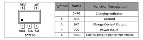
Fig. 2 – LTH7R IC Pinout
When the power supply is removed, the LTH7R IC automatically enters low-power mode, draining less than 2uA from the battery. This is extremely useful for preventing unnecessary discharge when the device is not in use.
When the LTH7R IC enters standby mode, the supply current is less than 25uA. The LTH7R IC can also monitor the charging current, has voltage detection features, automatic cycle charging, and has an indicator pin to signal the end-of-charge status and input voltage status.
🛠️ Detailed Technical Specifications
🔧 Hardware Features
- Programmable charging current up to 500mA
- No need for external MOSFET, sense resistor, reverse diode
- Constant current or constant voltage mode operation
- Integrated thermal protection function
- Preset charging voltage
- Standby current of only 20uA
- Trickle charging voltage of 2.9V
- Soft start that limits inrush current
- Adopts SOT23-5 package
📱 Practical Applications
- Batteries for microphones
- Lightweight cameras
- Cell phones, PDAs, MP3 players
- Bluetooth headphones
- Low-power IoT devices
- Portable electronic projects
- Rechargeable electronic toys
💡 Design Tip
The ability to program the charging current makes the LTH7R extremely versatile. For smaller batteries, use lower currents (100-200mA) to prolong battery life. For larger batteries or when you need fast recharges, you can use higher currents (up to 500mA).
🔧 Charging Current Programming
The PROG pin (pin 5) is the terminal for configuring the constant charging current and monitoring the charging current. The charging current can be programmed by connecting an external resistor from the PROG pin to ground.
In the pre-charge phase, the voltage of this pin is modulated at 0.1V; in the constant current charging phase, the voltage of this pin is fixed at 1V.
In all charging state modes, measuring the voltage of this pin allows estimating the charging current according to the following formula:
📖 General Formula:
Where I_bat is the charging current in mA and R_prog is the resistor in kΩ
Practical Example 1: Configuring for 300mA
To use in a charger that requires a current of 300mA, we can use the formula as follows:
- I_bat = 1000/ R_prog
- R_prog = 1000 / I_bat
- R_prog = 1000 / 300
- R_Prog = 3.3K
Practical Example 2: Configuring for 500mA (Maximum)
To use in a charger that requires the maximum current, 500mA, we can use the formula as follows:
- I_bat = 1000/ R_prog
- R_prog = 1000 / I_bat
- R_prog = 1000 / 500
- R_Prog = 2K
| Model | R_prog | I_bat |
|---|---|---|
| 1 | 10K | 100mA |
| 2 | 5K | 200mA |
| 3 | 3.3K | 300mA |
| 4 | 2.5K | 400mA |
| 5 | 2K | 500mA |
🎓 Technical Deep Dive
The ability to adjust the charging current through a simple external resistor makes the LTH7R extremely versatile. This approach allows the same basic circuit to be adapted for different battery capacities simply by changing the value of the R_prog resistor.
For batteries with capacity below 500mAh, it is recommended to use lower charging currents (100-200mA) to prolong battery life. For larger batteries, higher currents can be used to reduce charging time.
🔌 Circuit Electrical Schematic
In Figure 3, below, we present the complete schematic diagram of our Programmable 4.2V Battery Charger with current up to 500mA using the LTH7R IC. Think of this schematic as the “treasure map” that will guide your assembly!
All circuit components are of the SMD (Surface-Mount Device) type, which guarantees an extremely compact design. The power input is made by direct soldering on the PCB, making it perfect for projects where space is a precious resource.
⚠️ Expert Note
The capacitors are SMD electrolytic type. However, if you have access to tantalum capacitors, you can use them! They offer better performance and a lower profile, further optimizing the physical space of your project.
One of the great advantages of this circuit is its power supply versatility. It supports an input voltage between 4.4V and 7V, with the recommended value being 5V. This is excellent news, as it means you can charge your battery directly from a USB port on your computer or using common cell phone chargers!

Fig. 3 – Electrical Schematic of the Programmable 4.2V Charger, 500mA using LTH7R IC
🔗 Explore More Amazing Projects
Did you like this project? Then you’ll love exploring other charger circuits we’ve prepared. Each with its particularities and ideal applications!
-
🔋 3.7V Li-Ion Battery Charger with MCP73831
A compact and efficient alternative for small-scale projects.
-
⚡ Simple 12V Battery Charger with Automatic Indicator
Perfect for lead-acid batteries in security or automotive systems.
-
🛡️ Lithium (Li-Ion) Battery Charger using LP2951
Discover a robust and reliable approach for your charging needs.
-
🔧 12V Automatic Lead-Acid Battery Charger with LM350
A classic, powerful project ideal for higher capacity batteries.
🖨️ Printed Circuit Board (PCB)
To make your life easier, in Figure 4, we provide the PCB files – Printed Circuit Board. The files are in GERBER, PDF, and PNG formats, covering all your needs, whether for home assembly or to send to a professional fabrication.
And best of all: the files are available for free download directly from the MEGA server, through a direct link, without any complication or redirection!

Fig. 4 – PCB of the Programmable 4.2V Battery Charger, Current up to 500mA using LTH7R IC
📥 Direct Download Link
To download the necessary files for assembling the electronic circuit, just click on the direct link provided below:
Download Link: PCB Layout, PDF, GERBER, JPG
🤔 Frequently Asked Questions (FAQ)
To ensure your project is a success, we’ve compiled some of the most common questions about this charger. Check them out!
Can I use this charger for NiMH batteries?🔽
No. This circuit was designed specifically for lithium-ion (Li-Ion) and lithium-polymer (LiPo) batteries, which require a constant charging voltage of 4.2V. NiMH batteries use a different charging method.
What if I use a different value R_prog resistor?🔽
The charging current will be adjusted according to the formula I_bat = 1000 / R_prog. A higher value resistor will result in a lower current, and vice versa. Make sure to use a value that does not exceed the 500mA maximum of the IC.
Is it safe to leave the battery charging overnight?🔽
Yes! The LTH7R has an automatic cutoff. When the battery reaches full charge (the current drops to 1/10 of the programmed value), the circuit stops the charging process, preventing overcharging.
👋 Conclusion and Next Steps
Building your own programmable battery charger is an incredibly rewarding project that combines electronic theory with a practical and extremely useful application. With the LTH7R IC, you have in your hands a professional, safe, and compact solution to power your projects.
Now that you have all the information, the schematic, and the PCB files, the next step is up to you! Assembling this circuit will not only enhance your skills with SMD components but also give you a valuable tool for your lab or for your next inventions.
✨ Our Gratitude and Next Steps
We sincerely hope this guide has been useful and enriching for your projects! Thank you for dedicating your time to this content.
Your Feedback is Invaluable:
Have any questions, suggestions, or corrections? Feel free to share them in the comments below! Your contribution helps us refine this content for the entire ElCircuits community.
If you found this guide helpful, spread the knowledge!
🔗 Share This Guide
Best regards,
The ElCircuits Team ⚡


Parabéns pelo site,é de fácil compreensão,conteúdo vasto,forte abraço do Paulo aqui do Brasil.