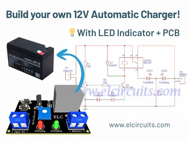
12V Automatic Battery Charger with LED Indicator + PCB (Simple & Efficient)
 |
| Simple 12V Battery Charger, automatic with charging indicator + PCB |
Hello, electronics enthusiasts!
Today we’re going to dive into the fascinating world of smart battery chargers. If you’ve ever been frustrated with batteries that don’t charge completely or with charging processes that require constant supervision, this project is for you!
We’re going to build an automatic 12V battery charger with visual indicators for charging and full charge. Best of all? This is a project extremely simple to assemble, perfect for those starting out in electronics or for hobbyists who want a practical and efficient solution.
💡 Expert Tip: This charger works with input voltage of 110V or 220V, depending on the power supply you use. The charging time will vary according to the power supply capacity and battery type.
⏱️ Calculating Charging Time
One of the most common questions is: “How long will it take to charge my battery?” Let’s solve this with a simple formula. Although we don’t take into account factors like battery internal resistance or charger fluctuations, this calculation will give us an excellent approximation.
Let’s use a practical example: you have a 12V 7Ah UPS battery, and your power supply provides 3A. How to calculate?
📐 Calculation Formula:
- B = Battery Capacity (in Ampere-hours)
- F = Power Supply Current (in Amperes)
- C = Charging Time (in hours)
- C = B/F = C = 7/3 = 2.33 hours
That is, your battery will take approximately 2 hours and 33 minutes to charge completely. If your power supply has a different current, just replace the values in the formula!
| Battery Capacity | Power Supply Current | Approx. Charging Time |
|---|---|---|
| 7Ah | 1A | 7 hours |
| 7Ah | 2A | 3.5 hours |
| 7Ah | 3A | 2.3 hours |
🔌 Circuit Schematic Diagram
The schematic diagram of the circuit Simple 12V Battery Charger, automatic with charging indicator + PCB is shown in Figure 2 below. This is a fairly simple circuit, with a basic to intermediate technical knowledge level for assembly. |
| Fig. 2 – Electronic Schematic of Simple Automatic 12V Battery Charger |
⚠️ Critical Point: Power Supply Voltage
It is essential that the power supply provides 20% more voltage than the battery. For example, if your battery is 12V, the power supply should have 14.4V. It may vary a little less, like 13.2V (10% above the battery voltage), but never use a 12V power supply to charge a 12V battery.
Why? Without this potential difference, there will be no effective charge. The battery may receive a small charge if it’s below 12V, but it will never charge completely.
Special recommendation: Check out our tutorial on how to adapt ATX power supplies for this purpose:
How to Modify ATX Power Supply to 13.6v, 22 Amperes
With this adapted power supply, you’ll have the ideal voltage for your charger to work perfectly!
🔗 Related Content
If you liked this project, you might also be interested in these other articles:
🧾 Bill of Materials:
| Component | Description |
| Q1 | General purpose NPN Transistor (C1815, BC548 etc.) |
| D1, D2, D3 | 1N4007 Diodes |
| R1 | 1/4W 10K Resistor (brown, black, orange) |
| R2 | 1/4W 100 Ohms Resistor (brown, black, brown) |
| R3 | 1/4W 1K2 Resistor (brown, red, red) |
| P1 | 10K Potentiometer or Trimmpot |
| RL1 | 12V 10A Relay, 5 pins |
| LED1, LED2 | 3mm LEDs (one Red and one Green) |
| Miscellaneous | Printed circuit board, soldering iron, solder, wires, etc. |
⚡ How to Use the 12V Battery Charger
Now that you’ve assembled your circuit, let’s learn how to use it correctly. Follow these steps to ensure efficient and safe charging:
🔧 Step-by-Step Configuration
- Circuit Check: First of all, carefully check if there are no wrong parts, diodes with reversed polarity or shorts in the connections.
- Power Supply Connection: Connect the positive of the power supply to the +VCC input of the circuit and the negative to the charger ground.
- Voltage Adjustment: Use a multimeter on the DC volts scale at the charger output. Adjust the potentiometer to set the trigger voltage limit.
- Maximum Voltage Definition: For 12V batteries, the full charge voltage is usually between 13.2V to 14.4V. Adjust to the desired value.
- Battery Connection: Connect the battery and wait for the charging process.
When the charger reaches the “voltage limit” that you adjusted, it will trigger the relay and light up the green LED, indicating that the battery has been fully charged. It’s that simple!
🔊 Extra Tip: Adding a Sound Indicator
How about making your charger even more functional? If you have a 12V buzzer lying around, you can easily add it! Connect the positive of the buzzer to the Relay output (where the green LED is) and the negative directly to ground.
Ready! Now you have an automatic charger with visual and sound indication of full charge. Perfect for when you’re away or busy with other tasks!
🖨️ Printed Circuit Board (PCB) to Download
In Figure 3 below, we are providing the PCB in GERBER, PDF and JPEG files, for those who want to do a more optimized assembly, whether at home or at a specialized company. You can download the files for free through the direct link in the Download option below.
 |
| Fig. 3 – Printed Circuit Board with Component Layout |
📥 Links to Download Files
🎯 Maintenance and Safety Tips
To ensure proper functioning and longevity of your charger, here are some important tips:
⚠️ Safety Recommendations
- Never charge damaged or leaking batteries – This can cause short circuits and even explosions.
- Keep the charger in a ventilated place – The heat generation process can damage components if there is not adequate ventilation.
- Check the polarity – Connecting the battery inverted can damage both the battery and the charger.
- Don’t overcharge – Although the circuit is automatic, it’s always good to periodically check the process.
🔄 Applications and Possible Improvements
Your new 12V battery charger can be used in various situations:
💡 Application Ideas
- Keep UPS batteries always charged
- Charge alarm system batteries
- Maintenance of vehicle batteries parked for long periods
- Recharging solar power system batteries
- Powering electronic projects that require batteries
Possible improvements: You can add a digital display to show the current battery voltage, implement an overcurrent protection system, or even create a portable version with its own case.
🤔 Frequently Asked Questions (FAQ)
Can I use this charger for batteries of other values?🔽
This circuit was designed specifically for 12V batteries. For other values, modifications in components and voltage adjustment would be necessary.
Why doesn’t my green LED light up even after hours of charging?🔽
Check if the adjustment voltage is correct and if the power supply is providing adequate voltage. It may also be that the battery is defective and cannot reach the full charge voltage.
Is it normal for the battery to heat up during charging?🔽
Slight heating is normal, but if the battery gets excessively hot, interrupt the process and check the connections. Overheating can indicate problems with the battery or circuit.
👍 Did you like this project? Share your experience!
Leave your comment below telling us how it was to assemble your charger, or if you have any questions, we’re here to help! Your experience can help other electronics enthusiasts.
✨ Our Gratitude and Next Steps
We sincerely hope this guide has been useful and enriching for your projects! Thank you for dedicating your time to this content.
Your Feedback is Invaluable:
Have any questions, suggestions, or corrections? Feel free to share them in the comments below! Your contribution helps us refine this content for the entire ElCircuits community.
If you found this guide helpful, spread the knowledge!
🔗 Share This Guide
Best regards,
The ElCircuits Team ⚡

 Português
 Español


