 Português
 Español
Rechargeable Emergency LED Light with LM350 IC + PCB: Full DIY Guide
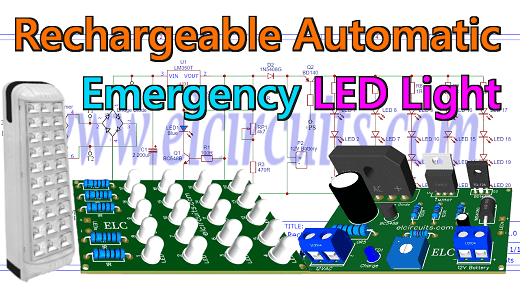
Fig. 1 – How To Make Rechargeable Emergency LED Light Using LM350 IC with PCB
Crafting a Rechargeable Emergency LED Light with LM350 IC: Step-by-Step Guide with PCB Implementation
You know that night when the power grid collapses and the power goes out, so we need a light to illuminate the darkness.
That’s when we realized that we would need some equipment that could light up that darkness…
In this article, we are going to assemble a Rechargeable Automatic Emergency LED Light circuit that when the power goes out, it activates the set of LED lamps automatically using a rechargeable 12V battery.
How the Circuit works
The Automatic Illuminator circuit is divided into three distinct parts:
1️⃣ The first part:
It’s pretty obvious, we have the 220Vac or 110Vac voltage coming from the mains, and we need to convert it to 12Vac. For this, we use a 220V/12Vac transformer. The output of the 12Vac transformer, it is connected to a diode bridge to rectify the AC voltage to DC, and the 2200uF capacitor to filter this voltage.
2️⃣ The second part:
It is a 12V battery charging stage, it works simply as a charger, it has a status LED that when charging it stays on, and when charged the LED goes off.
The circuit uses the LM350T voltage regulator. The output current of the LM350 is 3 amps, it is necessary to adjust the output voltage through the trimpot of 4.7K, this voltage must be adjusted according to the battery used.
In some batteries this voltage is 13.8V, in others it is 14.4V, this is always described together in the general battery information.
For those who follow us here on our site, you may have already noticed that the 12V battery charger circuit is very similar to an article that we have already done here on our site, you can check it out by clicking on this link.
3️⃣ The Third part:
It is a control circuit composed of a BD140 PNP transistor, which works as a drive circuit, when there is power on the grid.
The voltage from the source passes through the 1K base current limiting resistor, and causes the transistor to stay open, keeping the light off, as soon as the voltage is cut off.
The transistor as a switch closes the circuit, slinging the battery to the set of 20 LEDs, turning the light on.
🔌 The Circuit Diagram
The complete schematic diagram of the power supply is shown below in Figure 2, it is a simple but complete adjustable symmetric power supply.
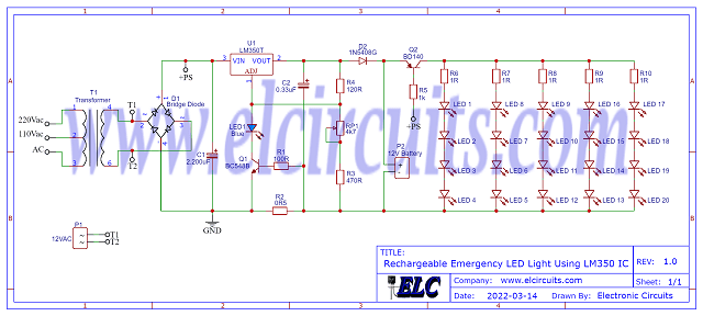
Fig. 2 – Schematic Diagram Rechargeable Emergency LED Light Using LM350 IC
You may be interested in:
- 3.7V Li-Ion Battery Charger Circuit using MCP73831 IC + PCB
- Simple 12V battery charger with automatic charging indicator + PCB
- Lithium (Li-Ion) Battery Charger using LP2951 IC + PCB
- USB 5V 4A Car Charger using 78S05 with PCB
⚡ The Power Transformer
The transformer should have as primary according to your local network, 110Vac or 220Vac. The secondary should be 12V, since when we pass through the rectification, this 12Vac voltage is transformed more or less into 16.9Vdc.
The transformer should have a current of 3 amps, in case you are going to use it with large batteries, such as 7A, 9A, etc…
If you are going to work with smaller batteries, it is up to you to place a transformer proportional to the total power of the LEDs and the battery used. The transformer configuration diagram is shown in Figure 4 below.
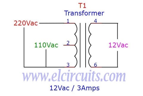
Fig. 3 – Schematic Diagram Transformer 110/220Vac to 12Vac 3Amps
🧮 Component List
- Semiconductors
- U1 …………………… LM350 Voltage Regulator
- Q1 …………………… BC548 NPN Transistor
- Q2 …………………… BD140 PNP Transistor
- D1 …………………… KBU4A – 4A Rectifier Bridge
- D2 …………………… 1N5408 Diode Rectifier
- LED1 to LED20 … Light Emitter Diode 5mm High Light
- LED1 ……………….. Light Emitter Diode 3mm (general use)
- Resistors
- R1 …………… 100Ω 1/8w Resistor (brown, black, brown, gold)
- R2 …………… 0.5Ω 5W Resistor (green, black, silver, gold)
- R3 …………… 470Ω 1/8w Resistor (yellow, violet, brown, gold)
- R4 …………… 120Ω 1/8w Resistor (brown, red, brown, gold)
- R5 …………… 1kΩ 1/8w Resistor (brown, black, red, gold)
- R6 to R10 … 1Ω 3W Resistor (brown, black, black, gold)
- RP1 …………. 4K7Ω Trimmer
- Capacitors
- C1 …… 2.200uF – 25V Electrolytic capacitor
- C2 …… 0.33uF – 25V Electrolytic capacitor
- Miscellanies
- P1, P2 ……. Connector 2 screw terminal 5mm 2 Pins
- T1 …………. Transformer Reduction 110/220ac to 12Vac (See Text)
- Others ……. Wires, Solders, pcb, heat sink, etc.
🖨️ Printed Circuit Board – Download
We provide the files with the PCB , the schematic, the PDF, GERBER and JPG, PNG and provide a direct link for free download and a direct link, “ MEGA.
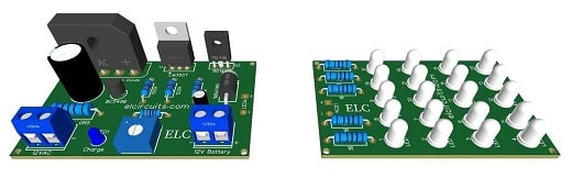
Fig. 4 – PCB – Rechargeable Emergency LED Light Using LM350 IC
📥 Files to Download, Direct Link:
Click on the direct link to download the files: Layout PCB, PDF, GERBER, JPG
✨ Our Gratitude and Next Steps
We sincerely hope this guide has been useful and enriching for your projects! Thank you for dedicating your time to this content.
Your Feedback is Invaluable:
Have any questions, suggestions, or corrections? Feel free to share them in the comments below! Your contribution helps us refine this content for the entire ElCircuits community.
If you found this guide helpful, spread the knowledge!
🔗 Share This Guide
Best regards,
The ElCircuits Team ⚡


