 Português
 Español
1.5V-28V 7.5A Adjustable Symmetrical Power Supply using LT1083 IC with PCB
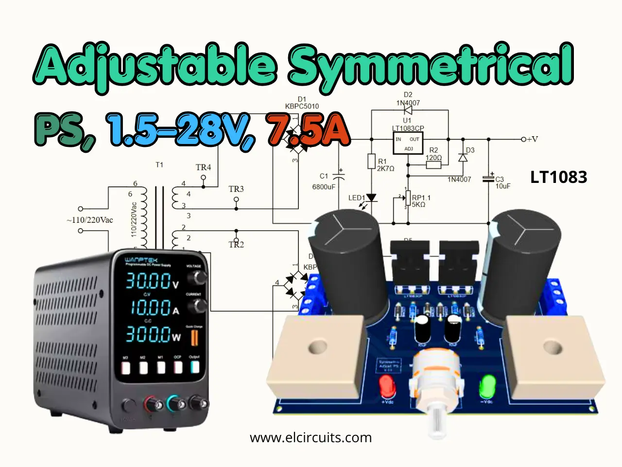
Fig.1 - 1.5V to 28V, 7.5 Amps Adjustable Symmetric Power Supply using IC LT1083 with PCB
Versatile Power at Your Fingertips: Build an Adjustable 1.5V to 28V, 7.5 Amps Symmetric Power Supply with IC LT1083 and PCB
This is a power supply designed to be used in a technical bench, based on the LT1083 integrated circuit, which is an adjustable 3-terminal positive voltage regulator.
Which provides a current of 7.5A in a variable output voltage range of 1.5 to 28V, and even has short circuit and over temperature protection.
The Circuit provides a symmetrical output, which pleases all of us engineers, technicians and designers, this type of power supply, as it brings us great efficiency for application in technical benches, mainly for testing audio amplifiers.
📖 LT1083 IC Description
The LT1083 positive adjustable regulator is designed to provide 7.5A with higher efficiency than currently available devices.
In Figure 2 - You'll find the description of the input, output and ground pins. There are other types of encapsulation, as this TO - 3P is the most common.
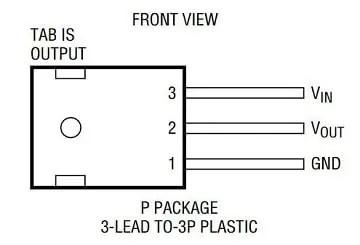
Fig. 2 - Pinout LT1083
All internal circuitry is designed to operate down to 1V input to output differential, and the dropout voltage is fully specified as a function of load current.
Dropout is guaranteed at a maximum of 1.5V at maximum output current, decreasing at lower load currents.
On-chip trimming adjusts the output voltage to 1%. The current limit is also trimmed, minimizing the stress on both the regulator and power source circuitry under overload conditions.
The LT1083 series devices are pin compatible with older three terminal regulators. A 10μF output capacitor is required on these new devices; however, this is usually included in most regulator designs.
Unlike PNP regulators, where up to 10% of the output current is wasted as quiescent current, the LT1083 quiescent current flows into the load, increasing efficiency.
🛠️ Features
- Three-Terminal 3.3V, 3.6V, 5V, 12V or Adjustable
- Output Current of 3A, 5A or 7.5A
- Operates Down to 1V Dropout
- Guaranteed Dropout Voltage at Multiple Current Levels
- Line Regulation: 0.015%
- Load Regulation: 0.1%
- 100% Thermal Limit Functional Test
- Adjustable Versions Available
🤔 How the Circuit Work
The circuit operation is quite simple, and its operation is applied with an artifice that we did to join two adjustable power sources into one.
Since we don't have "as far as I know", a regulator of the same negative line, like what happens with the regulators LM317, LM7812 and etc.
The bridges of diodes KBPC5010 D1 and D4, are responsible for rectifying the circuit, this diode bridge is able to support currents up to 50A.
I know it's an exaggeration, but it was what I had here, you can be putting with lower current, as the KBPC1510, for 15A, or the KBPC1010 for 10A.
The capacitors C1 and C3, are electrolytic capacitors responsible for filtering the circuit, we use them of 10,000uF, but if you don't have one you can put one of 8,000uF. Remembering that they have to be able to avoid Ripple in the power supply.
The resistors R1 and R3 are the limiters for LED1 and LED2, which are used as voltage signaling for the two sources.
The voltage that comes already rectified and filtered enters the Positive Voltage Regulators, as we can see in the circuit, they are identical circuits, and through the double potentiometer the output voltage regulation is done, ranging from 1.5V to 28V.
The diodes D2, D3, D5, and D6, are for reverse voltage protection that can arise from the circuit and damage the Regulators, and the diodes protect these voltages in the regulators.
The resistors R2 and R4, are responsible for the Feedback voltage, or feedback, they keep the output voltage stable, they are resistors that if you have conditions, put the ones with low error percentage, such as precision resistors with 1%.
And finally, the capacitors C2 and C4, are for spurious filter, if you can afford it, it is preferable tantalum capacitors.
🔌 The Circuit Diagram
The complete schematic diagram of the power supply is shown below in Figure 3, it is a simple but complete adjustable symmetric power supply.
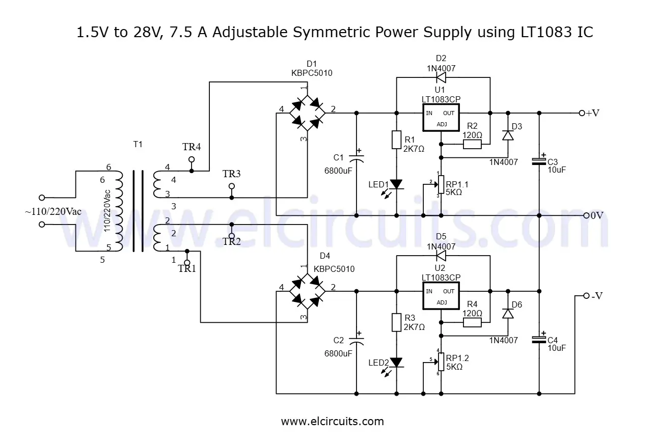
Fig. 3 - Schematic Diagram 1.5V to 28V, 7.5 Amps Adjustable Symmetric Power Supply using IC LT1083
You may be interested in:
- Switched Power Supply SMPS 13.8V 10A using IR2153 IC and IRF840, with PCB
- Adjustable Power Supply 1.2V to 37V, 6A, Short Circuit Protection with LM317 and TIP36 + PCB
- Symmetrical Adjustable Power Supply 1.25V to 47V 10 Amps with Short Circuit Protection + PCB
- Adjustable Power Supply 1.2 to 37V High Current 20A with LM317 and TIP35C + PCB
- Adjustable Power Supply 1.25v to 57V, 6 Amps with TIP36C + LM317HV + PCB
- Adjustable Power Supply 1.25v to 33V, 3 Amps with LM350 + PCB
- Stabilized Power Supply 13.8V High Current 10 Amps with PCB
⚡ The Power Transformer
The transformer must be symmetrical with center tape open, this means that it will to have two independent winding: "2 Wire + 2 Wire", as illustrated in Figure 4 below.
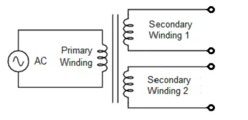
Fig. 4 - Symmetrical Transformer with Independent secondary winding
The transformer must be able to supply 8A at the symmetrical output. The primary voltage, "input voltage", must correspond to the voltage in your area; 110V or 220Vac.
The secondary voltage, "output voltage", should be 21Vac in each coil, because after rectification it will supply the circuit with 30Vdc.
🧮 Component List
- Semiconductors
- U1, U2 .................. LT1083 Voltage Regulator
- D1, D4 .................. KBPC5010 - 50A Rectifier Bridge *See Text
- D2, D3, D5, D6 .... 1N4007 Diode Rectifier
- LED1, LED2 ........ Light Emitter Diode (General Use)
- Resistors
- R1, R3 ....... 2K7Ω 1/8w Resistor (red, violet, red, gold)
- R2, R4 ....... 120Ω 1/8w Resistor (brown, red, brown, gold)
- RP1 ........... 5KΩ Double Potentiometer
- Capacitors
- C1, C3 ........ 10.000uF - 45V Electrolytic capacitor
- C2, C4 ........ 10uF - 45V Electrolytic capacitor
- Miscellanies
- P1, P2 ........ Connector 2 screw terminal 5mm 2 Pins
- P3 .............. Connector 3 screw terminal 5mm 3 Pins
- Others ....... Wires, Power Transformer, Solders, pcb, heat sink, etc.
🖨️ Printed Circuit Board - Download
We provide the files with the PCB, the schematic, the PDF, GERBER and JPG, PNG and provide a direct link for free download and a direct link, "MEGA".
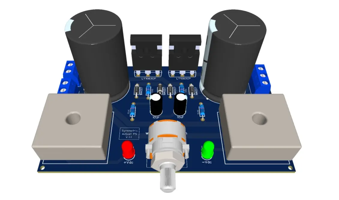
Fig. 5 - PCB - 1.5V to 28V, 7.5 Amps Adjustable Symmetric Power Supply using IC LT1083
📥 Files to Download, Direct Link:
Click on the direct link to download the files: Layout PCB, PDF, GERBER, JPG
✨ Our Gratitude and Next Steps
We sincerely hope this guide has been useful and enriching for your projects! Thank you for dedicating your time to this content.
Your Feedback is Invaluable:
Have any questions, suggestions, or corrections? Feel free to share them in the comments below! Your contribution helps us refine this content for the entire ElCircuits community.
If you found this guide helpful, share the knowledge!
🔗 Share This GuideBest regards,
The ElCircuits Team ⚡


