 Português
 Español
25A Solid State Relay (SSR) Circuit for 110/220V with BTA24-600 + PCB
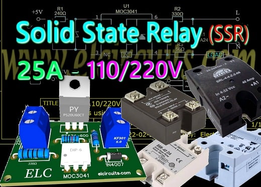
25A – 110/220V Solid State Relay (SSR) Circuits using Triac BTA24-600 With PCB
Efficient Power Control: Building 25A – 110/220V Solid State Relay (SSR) Circuits with Triac BTA24-600 and PCB
Solid State Relays (SSR) are nothing new, but making your own SSR is priceless! With it we can connect to digital control devices such as; Arduino, PIC, ESP, CLP, Raspberry, etc.
Besides that, we can spend a fraction of the price of a commercial relay if we make our own SSR relay, and still have in our hands control that if something goes wrong, we can repair it without too much trouble.
🧲 The Solid State Relay
A Solid State Relay is similar to switching relays, they all function as a switch that is controlled by an input voltage or current, isolated from the output.
The basic difference is that Solid State Relay, or (SSR), has no moving parts, but uses the electrical and optical properties of solid-state semiconductors.
Electromechanical Relays (EMR), on the other hand, use coils, magnetic fields, springs, and mechanical contacts to operate and switch through a supply voltage.
Our circuit uses few external components, and is easy to assemble, the components are easy to acquire in the market, and basically there are two:
- The isolation circuit formed by the MOC3041optical isolator.
- The power control formed by the BA24-600 TRIAC, they will be explained just below.
⚠️ CAUTION!!! ⚠️
This circuit works directly connected to the 110/220V electrical network, and has a high power load, any carelessness, or wrong connections, error in the project, or any other occasion, can lead to irreversible damage. We are not responsible for any type of event. If you do not have enough experience to assemble this circuit, do not do it, and if you do, when testing, be sure to have the proper protections and be accompanied by someone else.📚 BTA24 Description
Available either in through-hole or surface-mount packages, the BTA24 TRIAC is suitable for general purpose AC switching. They can be used as an ON/OFF function in applications such as static relays, heating regulation, induction motor starting circuits… or for phase control operation in light dimmers, motor speed controllers. The snubber-less versions (BTA/BTB…W and T25 series) are specially recommended for use on inductive loads, thanks to their high commutation performances. By using an internal ceramic pad, the BTA series provides voltage insulated tab (rated at 2500V RMS) complying with UL standards.🧷 6-Pin DIP Zero-Cross Opto-isolators Triac Driver Output
(400 Volts Peak)
The MOC3041, MOC3042 and MOC3043 devices consist of gallium arsenide infrared emitting diodes optically coupled to a monolithic silicon detector performing the function of a Zero Voltage Crossing bilateral triac driver. They are designed for use with a triac in the interface of logic systems to equipment powered from 115/220 Vac lines, such as solid–state relays, industrial controls, motors, solenoids and consumer appliances, etc.- Simplifies Logic Control of 115 Vac Power
- Zero Voltage Crossing
- dv/dt of 2000 V/μs Typical, 1000 V/μs Guaranteed
🔌 Solid State Relay Circuit
The 25A – 110/220V Solid State Relay (SSR) Circuits using Triac BTA24-600 circuit diagram is shown in Figure 2 below. It uses a 25 Amp TRIAC BTA24-600, this is enough to handle loads up to a little over 5.500W, obviously using a isolated heat sink.
Fig. 2 – 25A – 110/220V Solid State Relay (SSR) Circuits using Triac BTA24-600
💡 Basic Components Function
- Diode D1, is used for reverse voltage protection, it inhibits reverse voltage.
- Resistor R1 of 240 ohm, limits the input current to the internal LED of the MOC.
- Resistor R2 of 330 ohms for 1W, it serves to limit the supply current to the MOC‘s internal DIAC.
- Resistor R3 of 56 ohm, prevents any di/dt current when the TRIAC is off, eliminating false triggering.
🧮 Components List
- Semiconductors
- Q1 …. BTA24-600 Triac
- U1 …. MOC 3041 opto-isolator
- D1 …. 1N4007 Diode
- Resistor
- R1 …. 240Ω (red, yellow, brown, gold)
- R2 …. 330Ω (orange, orange, brown, gold)
- R3 …. 56Ω (green, blue, black, gold)
- Miscellaneous
- P1, P2 …. 2-pin PCB soldering terminal blocks (Optional)
- Others …. PCB, heat sink, wires, etc.
🖨️ Printed Circuit Board – Download
We are offering the PCB – Printed Circuit Board, in GERBER, PDF and PNG files, for you who want to do the most optimized assembly, either at home. If you prefer in a company that develops the board, you can download the files in the Download option below.
Fig. 3 – PCB – 25A – 110-220V Solid State Relay (SSR) Circuits using Triac BTA24-600
📥 Files to Download, Direct Link:
✨ Our Gratitude and Next Steps
We sincerely hope this guide has been useful and enriching for your projects! Thank you for dedicating your time to this content.
Your Feedback is Invaluable:
Have any questions, suggestions, or corrections? Feel free to share them in the comments below! Your contribution helps us refine this content for the entire ElCircuits community.
If you found this guide helpful, spread the knowledge!
🔗 Share This GuideBest regards, The ElCircuits Team ⚡


