 Português
 Español
Adjustable Power Supply 1.25V–57V 6A using TIP36C + LM317HV + PCB
Adjustable Power Supply 1.25v to 57V, 6 Amps using TIP36C + LM317HV
The LM317HV is an adjustable 3-terminal positive voltage regulator capable of supplying 1.5 A or more currents over a 1.25V to 57V output voltage range. It requires only two external resistors to set the output voltage. The LM317HV is packaged in standard transistor packages that are easily mounted and handled.
However, the LM317HV supports high voltage, but the current is still low, only 1.5A, our circuit, we are increasing a drive circuit to increase the current we need to 6 Amps, with three TIP36C transistors, which provides an adjustable output voltage between 1.25v to 57 volts, with a current of 6 Amps, which is enough for a bench power supply.
The Circuit Diagram
The schematic electrical diagram, which follows in Figure 2 below, it’s very simple, first one, we have the voltage input that comes through connector J1, which enters through resistor R1, that as long as there is no current greater than the one calculated, there is no drop of voltage in R1, more if the current increases, there will be a voltage drop of approximately 0.6V, which will cause the transistors to saturate, causing the current to pass through the power transistors.
The capacitor C1 has the objective of attenuating the interference of the ripples and their stability. Capacitor C2 has the function of eliminating high interference, and capacitor C3 has the function of constancy to decrease the ripple and stability of the power supply.
P1, is a 5K analog potentiometer, if you don’t have 5K you can put 4.7K, which is more commercial, the diodes D1 and D2 are to avoid reverse voltage over the Integrated Circuit U1, and in the transistors, resistors R3, R4 and R5, are impact resistors, which attenuate the difference between the transistors and prevent one from working more than the other.
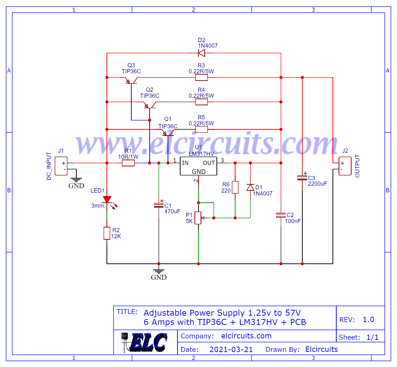
Fig. 2- Adjustable Power Supply Schematic LM317HV + TIP36
You may be interested in:
- Switched Power Supply SMPS 13.8V 10A using IR2153 IC and IRF840, with PCB
- Adjustable Power Supply 1.5V to 28V, 7.5A With IC LT1083 + PCB
- Adjustable Switching Power Supply 5.1 to 40V, 2.5 Amp using L4960 + PCB
- Adjustable Power Supply 1.2V to 37V, 6A, Short Circuit Protection with LM317 and TIP36 + PCB
- Symmetrical Adjustable Power Supply 1.25V to 47V 10 Amps with Short Circuit Protection + PCB
- Adjustable Power Supply 1.2 to 37V High Current 20A with LM317 and TIP35C + PCB
- Adjustable Power Supply 1.25v to 33V, 3 Amps with LM350 + PCB
- Stabilized Power Supply 13.8V High Current 10 Amps with PCB
Components list
- U1………………. LM317HV – Integrated circuit, voltage regulator
- Q1,Q2,Q3 ……… TIP46C Power Transistor
- D1, D2 ………….1N4007- Silicon rectifier diodes
- C1 ……………… 470 uF – 65V – Electrolytic capacitor
- C2 ……………… 100 nF Ceramic capacitor
- C3 ……………… 2200 uF – 65V – Electrolytic capacitor
- R1 ……………… 10 ohms – 1W – brown, black, black, gold
- R2 ……………… 2K ohms – 1/4 W – red, black, orange, gold
- R3, R4, R5 .……. 0.22 ohms – 5W – red, red, silver, gold
- R6 ……………… 220 ohms – 1/4W – red, red, brown, gold
- P1 ……………… 5 K ohms or 4,7 k ohms – Linear potentiometer
- J1, J2 …….……. Kre Block Terminal Terminal 2-Way Double Connector
- Others …………… Printed Circuit Board, tin, wire, etc.
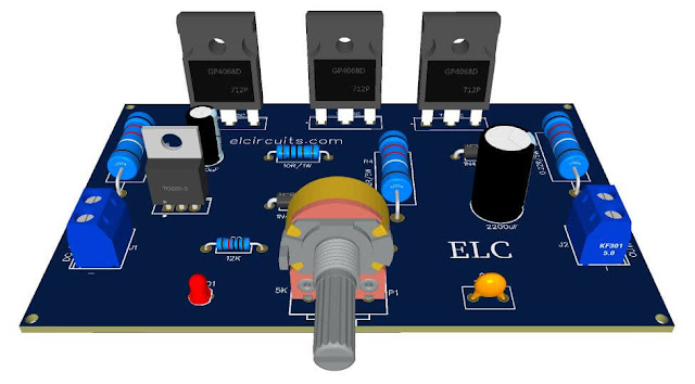
PCB – Printed Circuit Board
We are offering to Download the link with the printed circuit board printing files, they are; Gerber, PDF layout, PNG, all the files with a direct link to Mega.
Direct link to download
Click in the link below to download the Files: PCB Layout, PDF, GERBER
✨ Our Gratitude and Next Steps
We sincerely hope this guide has been useful and enriching for your projects! Thank you for dedicating your time to this content.
Your Feedback is Invaluable:
Have any questions, suggestions, or corrections? Feel free to share them in the comments below! Your contribution helps us refine this content for the entire ElCircuits community.
If you found this guide helpful, spread the knowledge!
🔗 Share This Guide
Best regards,
The ElCircuits Team ⚡


