 Português
 Español
Adjustable Power Supply 1.25V–33V 3A with Short-Circuit Protection + PCB
Adjustable Power Supply 1.25v to 33V, 3A with Short-Circuit Protection using LM350
Hello, electronics enthusiasts! 👋
If you’re like me, you know that a good adjustable power supply is the heart of any electronics workbench. It’s that indispensable tool that allows us to test projects, power prototypes, and diagnose circuits with precision. Today, we’re going to dive into a project that will transform your workbench: a robust, versatile power supply, and best of all, with intelligent protection!
Imagine having in your hands a power supply capable of delivering 1.25V to 33V with up to 3 Amperes of current, all with protection against short-circuit and overheating. Sounds like a dream? Not at all! This is exactly what we’re going to build together using the fantastic LM350.
🔍 Getting to Know the LM350: The Heart of Our Power Supply
The LM350 isn’t just another voltage regulator. This component is a true workhorse in the world of electronics, capable of providing 3.0 Amperes in an output range of 1.2 V to 33 V. What makes this IC special is its extreme simplicity: we only need two external resistors to adjust the output voltage!
Teacher’s tip: Think of the LM350 as a “brain” for your power supply. It constantly monitors the output voltage and makes necessary adjustments to keep it stable, even when the load varies. It’s like having an attentive assistant taking care of the health of your circuits!
But the LM350 isn’t just powerful, it’s also smart. It comes with protection features that make it practically disaster-proof:
- Internal current limiting – Protects your components from current spikes
- Thermal shutdown – Automatically shuts off if overheating
- Safe operating area compensation – Ensures safe operation under all conditions
LM350 Technical Specifications
| Specification | Value |
|---|---|
| Maximum output current | 3.0 A (guaranteed) |
| Output voltage range | 1.2 V to 33 V (adjustable) |
| Load regulation | Typically 0.1% |
| Line regulation | Typically 0.005% / V |
| Thermal protection | Internal |
| Short-circuit protection | Internal with current limiting |
With these specifications, the LM350 meets a wide variety of applications, from simple voltage regulators for digital circuits to precision current sources for more demanding projects.
🔌 Circuit Electrical Schematic
Now that we know the protagonist of our story, let’s get to what matters: the electrical schematic! I’ve prepared a detailed diagram showing each component in its proper place. Don’t worry, the circuit is simpler than it looks!
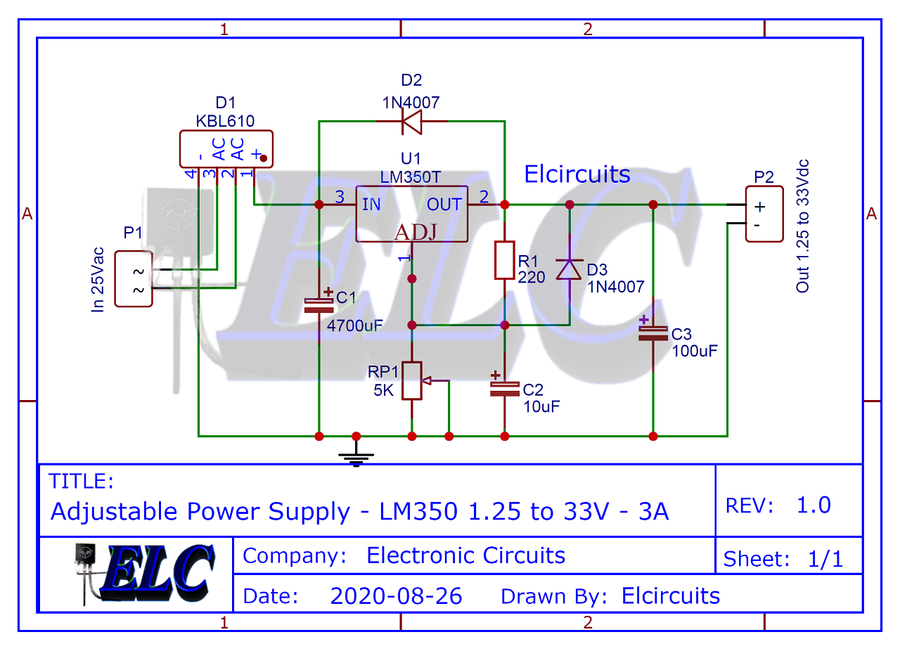
Fig. 2- Schematic Diagram Adjustable Power Supply Schematic LM350
⚠️ Safety note: Before starting the assembly, remember that we’re working with potentially dangerous voltages. Always disconnect the power supply from the mains before handling components and use insulated tools when necessary.
Let’s analyze each part of the circuit:
Rectification Stage
First, we have the GBJ2510 bridge rectifier, a robust bridge of 25 Amperes at 1000 Volts. It’s responsible for converting the AC voltage from the transformer into pulsating DC voltage. You can use any bridge rectifier that supports at least 4 Amperes and 50 Volts.
Filtering Stage
After rectification, we enter the filtering stage, where capacitors C2 (4700 µF) and C3 (100 µF) work their magic. They are responsible for smoothing the pulsating voltage, transforming it into a more stable DC voltage. Think of them as small energy reservoirs that fill in the “valleys” of the rectified wave.
Regulation Stage
Here comes our star, the LM350! It receives the filtered voltage and regulates it to the desired value, adjusted by the potentiometer P1 (5K or 4.7K). Diodes D2 and D3 (1N4007) act as protection for the IC, preventing damage during startup when capacitor C3 is discharged.
💡 Technical curiosity: Capacitor C1 is crucial for the regulator’s stability. It attenuates interference and oscillations that could compromise the power supply’s performance. Without it, you might observe instability in the output voltage, especially with variable loads.
Transformer
T1 is a transformer with input compatible with your local network (110V or 220V) and secondary of 25V with a minimum current of 3A. This transformer is responsible for reducing the mains voltage to a level suitable for our circuit.
📋 Bill of Materials
To make your life easier, I’ve prepared a complete list of all necessary components. Just print it and take it to your favorite electronics store!
- IC1 – LM350T – Voltage regulator integrated circuit
- D1 – GBJ2510 – Silicon bridge rectifier diode
- D2, D3 – 1N4007 – Silicon rectifier diodes
- C1 – 0.1 µF – Ceramic capacitor
- C2 – 4700 µF – 50V – Electrolytic capacitor
- C3 – 100 µF – 50V – Electrolytic capacitor
- R1 – 220 ohms – Resistor (red, red, brown, gold)
- T1 – Transformer with primary according to local network and secondary of 25 Vac with minimum current of 3A
- RP1 – 4.7 k ohms – Trimpot or potentiometer
- Others – Wires, solder, printed circuit board, heat sink for LM350, etc.
✅ Assembly tip: Don’t forget to use an adequate heat sink for the LM350! Even with internal thermal protection, a good heat sink will ensure greater efficiency and component life, especially when operating at currents close to maximum.
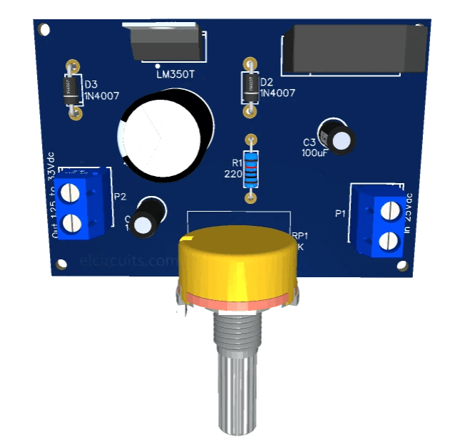
🖨️ Printed Circuit Board (PCB)
To make your life easier, we’ve provided the PCB – Printed Circuit Board files. The files are available in GERBER, PDF, and PNG formats, covering all your needs, whether for a homemade assembly or to send to a professional fabrication.
And best of all: files are available for free download directly from the MEGA server, through a direct link, without any complications or redirects!
📥 Direct Download Link
To download the necessary files for assembling the electronic circuit, just click on the direct link provided below:
DOWNLOAD PCB FILES (Layout PCB, PDF, GERBER, JPG)
🔧 Assembly and Testing Tips
Now that you have all the components and the board, here are some tips to ensure your power supply works perfectly:
- Check twice, assemble once: Before soldering any component, verify that you have all the items on the list and that they match the specified values.
- Start with smaller components: Soldering resistors, diodes, and smaller capacitors first makes the job easier and prevents accidents.
- Pay attention to polarity: Electrolytic capacitors and diodes have defined polarity. Inverting them can damage the components!
- Use solder flux: A little flux can work wonders for the quality of your solder joints, especially for beginners.
- Test in stages: Before connecting the LM350, check if the rectified and filtered voltage is correct. Then, with the LM350 installed, adjust the potentiometer and verify if the output voltage varies as expected.
💡 Practical Applications for Your New Power Supply
With your adjustable power supply ready, a world of possibilities opens up! Here are some ideas to explore the full potential of your new equipment:
- Component testing: Check LEDs, motors, solenoids, and other components at different voltages to find their ideal operating point.
- Powering prototypes: Provide the exact voltage needed for your Arduino, Raspberry Pi, and other platform projects.
- Repair electronics: Simulate the power conditions of devices under maintenance to diagnose problems safely.
- Educational experiments: Explore the characteristics of different electronic components by varying the voltage and observing the behavior.
- Battery charging: With some adjustments, you can create a custom charger for different types of batteries.
🤔 Frequently Asked Questions (FAQ)
To ensure your project is a success, we’ve compiled some of the most common questions about this power supply. Check it out!
Can I replace the LM350 with an LM317?🔽
Although the LM317 is electrically similar, it only supports 1.5A of maximum current, half the capacity of the LM350. If you don’t need more than 1.5A, replacement is possible, but remember to adjust the heat sink accordingly.
Is it possible to increase the maximum current to more than 3A?🔽
Yes! You can add power transistors in parallel with the LM350 to increase the current capacity. There are several circuits available that show how to make this modification, but it adds complexity to the project.
Why doesn’t my power supply adjust below 1.25V?🔽
The LM350 has an internal reference voltage of approximately 1.25V. This means the lowest voltage it can regulate is this value. To obtain lower voltages, you would need an additional circuit or a different regulator.
What heat sink should I use for LM350?🔽
The ideal heat sink depends on the difference between input and output voltage, and the current you intend to use. For operation at 3A with significant voltage difference, a large heat sink with forced ventilation (fan) is recommended. For lighter operations, a medium heat sink is sufficient.
Can I use a transformer with a different voltage than 25V?🔽
Yes, but this will affect the maximum output voltage. Remember that the maximum output voltage is approximately 2V less than the input voltage (after rectification and filtering). A 18V transformer would result in a maximum output voltage around 22-24V.
🔗 Additional Resources
If you liked this project, I’m sure you’ll love these other related articles:
- Switched Power Supply SMPS 13.8V 10A using IR2153 IC and IRF840, with PCB
- Adjustable Power Supply 1.5V to 28V, 7.5A using IC LT1083 + PCB
- Adjustable Switching Power Supply 5.1 to 40V, 2.5 Amp using L4960 + PCB
- Adjustable Power Supply 1.2V to 37V, 6A, Short Circuit Protection using LM317 and TIP36 + PCB
- Symmetrical Adjustable Power Supply 1.25V to 47V 10 Amps with Short Circuit Protection + PCB
- Adjustable Power Supply 1.2 to 37V High Current 20A using LM317 and TIP35C + PCB
- Adjustable Power Supply 1.25v to 57V, 6 Amps using TIP36C + LM317HV + PCB
- Stabilized Power Supply 13.8V High Current 10 Amps with PCB
For those who want to make a more powerful adjustable power supply, for example with 6 Amperes, we have this post about adjustable module at the link below:
🎉 Conclusion
Congratulations on making it this far! 🎊 With this project, you’ve not only built a high-quality adjustable power supply but also deepened your knowledge of power electronics and voltage regulators.
Remember that practice leads to perfection. If you encounter difficulties, don’t hesitate to consult our article again or search for video tutorials. The electronics community is vast and always willing to help!
🚀 Challenge for you: How about adding a digital display to your power supply to show the output voltage and current in real-time? Or implement a maximum current control for additional protection? Share your modifications with us in comments!
📢 Share and Interact!
Did you like this project? Do you have any questions or suggestions? Leave your comment below! We love to hear from our community and learn from your experiences.
✨ Our Gratitude and Next Steps
We sincerely hope this guide has been useful and enriching for your projects! Thank you for dedicating your time to this content.
Your Feedback is Invaluable:
Have any questions, suggestions, or corrections? Feel free to share them in the comments below! Your contribution helps us refine this content for the entire ElCircuits community.
If you found this guide helpful, spread the knowledge!
🔗 Share This Guide
Best regards,
The ElCircuits Team ⚡


