 Português
 Español
How to Wire LEDs for 110V or 220V: 6 Practical Circuits with Formulas
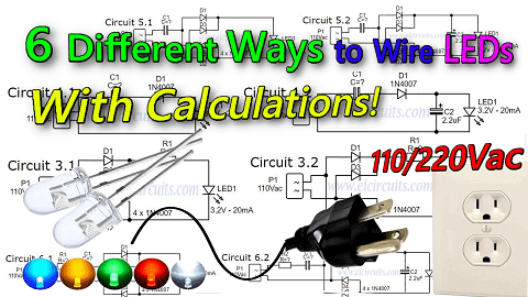
Fig. 1 – How to Wire LEDs in 110V or 220 Volts – 6 Different Circuits! Formulas & Calculations!
Illuminating Insights: Wiring LEDs for 110V or 220V – Explore 6 Distinct Circuits with Formulas and Calculations!
Today we will show you 6 different ways to wire 3mm or 5mm LEDs, which are low voltage DC components, into a 110V or 220V AC voltage grid!
We can use LEDs in several ways connected to 110V or 220V power grid, knowing that some types of connections bring advantages over others, and that each type has its characteristics that best fit each specification.
We will use some basic formulas to calculate the components in our circuit, for this we will use the capacitive reactance formula, and the Ohms Law formula.
So let’s start by showing the basic formulas that we will use with the models we made in this post. We’ll apply the basic formulas as needed, so we’ll start first by determining the supply voltage.
⚠️ CAUTION! ⚠️
As simple as the circuits presented are, it is important to know that the circuit is connected to direct mains voltage, this is extremely dangerous, an oversight or design error, can cause irreversible damage.
Be cautious when handling electrical voltage, if you have no electronics/electrical experience, do not do this circuit.
If you are experienced, do it with caution, and always have someone nearby, do not handle mains-connected equipment when you are alone.
We are not responsible for any damage that happens to you or others.
⚙️ The working voltage
In our country the working voltage is 110VAC, if your electrical network is 220VAC, just substitute the working voltage of your region in the formula.
It is necessary to know that our grid voltage has peak voltages, as showing in Figure 2 below, and for our safety we will use the peak to peak voltage (VPP) in our calculations.
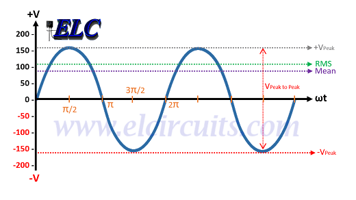
Fig. 2 – Peak to Peak 110Vac Calculation – VPP
🧮 The calculation is determined by the mathematical equation:
- VP = VAC * √(2)
As our power grid is 110VAC:
- VP = 110 * 1.414
- VP = 155.54VAC
If you use the 220VAC power grid:
- VP = 220V * 1.414
- VP = 311.08VAC
💡 The LED
- We will use a white LED, which in its specifications is 3.2V for 20mA, or 0.02A.
1️⃣ Determine the resistor resistance:
- V = R * I
2️⃣ Determine the Resistor’s Power:
- P = R * I²
3️⃣ Determine Capacitive Reactance:
Capacitive reactance is the opposition that a capacitor presents to the flow of current in AC circuits.
Capacitive reactance is represented by the notation Xc, and is expressed in ohms. To determine the capacitive reactance Xc, we will use the equation:
- XC = 1 / (2 π * F * C)
🧐 Knowing all the formulas that we will use in our circuits, let’s start with the simplest to the most complex.
✅ 1° Circuit:
This model is the simplest we have, and it is very often used in cheap electrical extensions of those Chinese products, and also as a Pilot lamp in equipment,…
The circuit presented has only one resistor R1, which limits the current that passes through the LED, and is connected in series with the LED, as we can see in Figure 3 below.
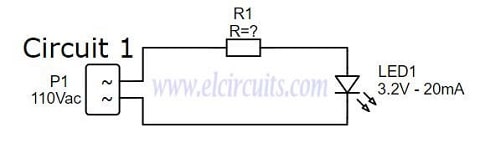
Fig. 3 – Wire LED in 110v or 220V Circuit 1 – ELC
Designing the Circuit
We need to determine the resistance to be used, for this we will use the ohms law formula:
General Formula:
- V = R * I
Applying the formula to our circuit:
- R = (VS – VL) / I
VS = Peak mains voltage, which is 155.54Vac
VL = Voltage of the LED, which is 3.2V
IL = The LED current, which is 0.02A
Then:
- R = (155.54 – 3.2) / 0.02
- R = 152.34 / 0.02
- R = 7.617Ω
As we know, when it comes to electronic components, there is the tolerance of the components that make up the circuit, such as the tolerance of the resistor, the LED, and the variations “tolerance” coming from the Power grid.
For this reason, we give a tolerance margin of more or less 40% more in the load resistor, that is:
- 7.617Ω + 40% = 3.047Ω
- 7.617Ω + 3.047Ω = 10.6638Ω or 10.66KΩ
- That is, the value of the closest commercial resistor, knowing that we always take the closest one with the highest value is 12KΩ.
We now need to determine the power of the resistor, for this we will use the ohms law formula:
General Formula:
- P = R * I²
Then:
- P = 12.000 * 0.02²
- P = 4.8W
🆗 Project Finished – Circuit 1
We finish here the development of our circuit 1, the calculated values we will have:
- LED1 ……. 3.2V / 20mA Light Emitting Diode
- R1 ………… 12K / 5W Resistor for 110V. (27K to 220V).
✔️ Advantages:
- It is a Simple and easy circuit to assemble
- Only 2 components
❌ Disadvantages:
- Voltage dissipation will be on the resistor (Joule effect)
- Consumption higher than necessary
- Circuit operating in half wave, LED half off
- Short LED lifetime, reverse voltage on LED
- Low Efficiency
✅ 2° Circuit:
This model is still quite simple, it is a circuit widely used also in cheaper electrical extensions of those Chinese products…
The circuit presented has a resistor R1, which limits the current that passes through the LED, and a Diode, which polarizes the AC voltage coming from the power grid, which is connected in series with the LED, as we can see in Circuit 2.1 in Figure 4 below.
We also have Circuit 2.2, which is the same circuit, but we have added a 2.2uF capacitor that serves to minimize the ripple voltage in the circuit.
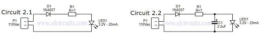
Fig. 4 – Wire LED in 110v or 220V Circuit 2 – ELC
Designing the Circuit
Just like the previous circuit, the calculations are the same, we already calculated the resistance, after all the process, it was 12K with 5W of power.
🆗 Project Finished – Circuit 2
Here we finish the development of our circuit 2, the calculated values are
- LED1 ……. Light Emitting Diode 3.2V / 20mA
- D1 ………… 1N4007 Diode
- C1 ………… 2.2uF / 25V Electrolytic Capacitor (Optional)
- R1 ………… 12K / 5W resistor for 110V. (27K at 220V).
✔️ Advantages:
- It is a simple and easy circuit to assemble
- Only 3 or 4 components
- Safer circuit for LED lifetime
❌ Disadvantages:
- Voltage dissipation will be on the resistor (Joule effect)
- Consumption higher than necessary
- Circuit operating in half wave, LED half off
- Low Efficiency
✅ 3° Circuit
This model, different from the previous one, adopts a rectifier bridge, this implies that the energy that comes to the LED, is no longer a half wave, but a full wave, which gives more brightness to the LED.
The circuit presented has a resistor R1, current limiter, and a bridge of diodes, which polarize the AC voltage that comes from the grid, and feeds the LED, as we can see in Circuit 2.1 in Figure 5 below.
We also have Circuit 2.2, which is the same circuit, but we add a 2.2uF capacitor that serves to minimize the ripple voltage in the circuit.
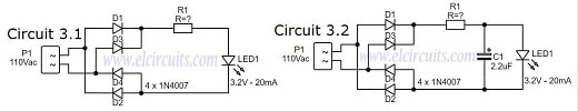
Fig. 5 – Wire LED in 110v or 220V Circuit 3 – ELC
Designing the Circuit
Just like the previous circuit, the calculations are the same, we already calculated the resistance, after all the process, it was 12K with 5W of power.
🆗 Project Finished – Circuit 3
Here we finish the development of our circuit 2, the calculated values are
- LED1 ……. Light Emitting Diode 3.2V / 20mA
- D1 ………… 4 x 1N4007 Diode, or a diode bridge any model
- C1 ………… 2.2uF / 25V Electrolytic Capacitor (Optional)
- R1 ………… 12K / 5W resistor for 110V. (27K at 220V).
✔️ Advantages:
- It is a simple circuit to assemble
- Only 3 or 4 components
- Full wave, which gives more brightness to the LED.
- Safer circuit for LED lifetime
❌ Disadvantages:
- Voltage dissipation will be on the resistor (Joule effect)
- Consumption higher than necessary
- Low Efficiency
✅ 4° Circuit:
This model is simple, but works in a more efficient way, since the heat dissipation is no longer tied to the Current Limiting Resistor, which dissipated all the voltage in the previous circuits.
This circuit is widely used in Mosquito Bats, rechargeable flashlights, i.e. cheaper Chinese products.
In this circuit we replaced the current limiting resistor with a capacitor. When a capacitor is connected to an AC source, it allows current to flow in a circuit.
With the process of successive charge and discharge of a capacitor, it gives rise to a resistance, in the passage of current in the circuit, and this resistance is called capacitive reactance. With these properties, we can use the capacitor in our circuit as a resistor.
In the case of the capacitor, all of this energy is used, because the capacitor needs to charge and discharge, it “holds” the energy and therefore does not consume it, making the circuit much more efficient.
We also have Circuit 4.2, which is the same circuit, but we have added a 2.2uF capacitor that serves to minimize the ripple voltage in the circuit. The complete circuits are in Figure 6 below.
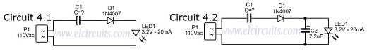
Fig. 6 – Wire LED in 110v or 220V Circuit 4 – ELC
Designing the Circuit
We need to determine the capacitive reactance to be used, for this we will use the Ohms’ Law formula, it is exactly the formula used to figure out the resistance of R1 in the previous circuits.
Remember: The V and I values are effective, so we will use the RMS voltage, not the VPP voltage.
General Formula:
- XC = (VS – VL) / IL
Applying the formula to our circuit:
- XC = (VS – VL) / I
- VS = Mains voltage, which is 110Vac
- VL = Voltage of the LED, which is 3.2V
- IL = The LED current, which is 0.02A
Then:
- XC = (110 – 3.2) / 0.02
- XC = 106.8 / 0.02
- XC = 5.340Ω or 5.3K
Since we have already found out the XC reactance which is 5.340Ω or 5.3KΩ, we can now calculate the current that this capacitor will supply to our circuit. We will use the same formula as in Ohms’ Law:
General Formula:
- I = VS / XC
- VS = Main voltagem in RMS
- XC = Capacitive Reactance in Ω
Applying the formula to our circuit:
- I = (VS – VL) / XC
VL = Voltage of the LED, which is 3.2V
- I = (110 – 3.2) / 5.340
- I = (106.8) / 5.340
- I = 0.02A
- I = 20mA
Knowing the resistance XC and current I values in the circuit, we need to determine the capacitance of the capacitor. We will do this as follows below:
General Formula:
- C = 1 / (2 π * F * XC)
Since capacitance is usually not expressed in Farad but in a submultiple, we will use the rewritten formula, so that we can use the capacitor value in µF and make our calculations easier.
Applying the formula to our circuit:
- C = 106 / (2 π * F * XC)
C = Capacitance that we need to know
π = Is a constant 3.14
XC = Capacitive Reactance, which is 5.340Ω
F = Main frequency, which is 60Hz
- C = 106 / (2 * 3.14 * 60 * 5.340)
- C = 106 / (6.28 * 60 * 5.340)
- C = 106 / (376.8 * 5.340)
- C = 106 / (2,012.112)
- C = 0.4969uF or 497nF
That is, the value of the closest commercial capacitor, knowing that we always take the closest one with the highest value is 560nF.
🆗 Project Finished – Circuit 4
We finish here the development of our circuit 4, the calculated values we will have:
- LED1 ……. Light Emitting Diode 3.2V / 20mA
- D1 ……….. 1N4007 Diode
- C1 ………… 560nF / 250V Polyester Capacitor
- C2 ………… 2.2uF / 25V Electrolytic Capacitor (Optional)
✔️ Advantages:
- No consumption of excess heat energy (Joule effect)
- It is simple circuit to assemble
- Only 3 or 4 components
- High Efficiency
- Safer circuit for LED lifetime
❌ Disadvantages:
- Circuit operating in half wave, LED half off
- High current in the initial steady state of the capacitor, causing those “pops” and sparks in the socket.
✅ 5° Circuit:
This model is a more complete and improved circuit, because it brings with it a diode bridge, improving efficiency even more, since the LED will no longer work for half a wave period, but for a full wave period.
This circuit is widely used in small luminaires, even in LED lamps, rechargeable flashlights, or in commercial products.
This circuit is the junction of circuits 3 and 4, thus forming an efficient circuit, with good LED brightness, with full wave, it is almost the perfect circuit.
The circuit presented has a diode bridge, which polarizes the AC voltage coming from the mains, which is connected in series with the LED, as we can see in Circuit 5.1 in Figure 7 below.
We also have Circuit 5.2, which is the same circuit, but we add a 2.2uF capacitor that serves to minimize the ripple voltage in the circuit.
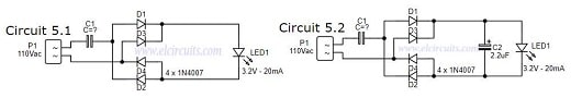
Fig. 7 – Wire LED in 110v or 220V Circuit 5 – ELC
Designing the Circuit
First you need to determine the capacitive reactance, which was already done in the previous circuit, the capacitance is 5.340Ω or 5.3K.
🆗 Project Finished – Circuit 5
We finish here the development of our circuit 5, the calculated values we will have:
- LED1 ……. Light Emitting Diode 3.2V / 20mA
- D1 ……….. 4 x 1N4007 Diode, or a diode bridge, any model
- C1 ……….. 560nF / 250V Polyester Capacitor
- C2 ……….. 2.2uF / 25V Electrolytic Capacitor (Optional)
✔️ Advantages:
- It is a simple circuit to assemble
- Only 3 or 4 components
- Safer circuit for LED lifetime
- No consumption of excess heat energy (Joule effect)
- High Efficiency
- Circuit operating in full wave, LED always on
❌ Disadvantages:
- High current in the initial steady state of the capacitor, causing those “pops” and sparks in the socket.
✅ 6° Circuit:
This model is more complete and, like the previous circuit, is more efficient. This circuit is widely used in small light fixtures, some LED lamps, rechargeable flashlights, and in some commercial products.
The circuit presented is identical to circuit 5, with the only difference that we put a resistor R1, that serve to limit the capacitor inrush current. A diode bridge, which polarizes the AC voltage coming from the mains, which is connected in series with the LED, as we can see in Circuit 6.1 in Figure 8 below.
We also have Circuit 6.2, which is the same circuit, but we have added a 2.2uF capacitor that serves to minimize the ripple voltage in the circuit.
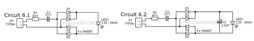
Fig. 8 – Wire LED in 110v or 220V Circuit 6 – ELC
🔌 Designing the Circuit
First you need to determine the resistance R1, the resistor value was chosen to limit the worst case inrush current to about 100mA which for safety, will be 5 times the current draw of the circuit, which will drop to less than 20mA in a millisecond as the capacitor charges.
In this case, we use ohms’ law to figure out what resistor we will use.
General Formula:
- V = R * I
Applying the formula to our circuit:
- R = (VS – VL) / I
- VS = Mains voltage, which is 110Vac
- VL = Voltage of the LED, which is 3.2V
- IL = Inrush current, which is 0.1A or 100mA
Then:
- R = (110 – 3.2) / 0.100
- R = 106 / 0.100
- R = 1,068Ω or ~1KΩ
Now, we need to determine the power of the resistor, for this we will use the ohms law formula:
General Formula:
- P = R * I²
Then:
- P = 1,068 * 0.02²
- P = 0.427W
That is, the value of the closest commercial power resistor, knowing that we always take the closest one with the highest value is 1/2W.
🆗 Project Finished – Circuit 6
We finish here the development of our circuit 5, the calculated values we will have:
- LED1 ……. Light Emitting Diode 3.2V / 20mA
- D1 ……….. 4 x 1N4007 Diode, or a diode bridge, any model
- R1 ……….. 1KΩ / 1/2W Resistor
- C1 ……….. 560nF / 250V Polyester Capacitor
- C2 ………… 2.2uF / 25V Electrolytic Capacitor (Optional)
✔️ Advantages:
- It is a simple circuit to assemble
- Only 3 or 4 components
- Safer circuit for LED lifetime
- No consumption of excess heat energy (Joule effect)
- High Efficiency
- Circuit operating in full wave, LED always on
❌ Disadvantages:
- Can be better, by putting a resistor in parallel as a capacitor, to discharge it…
✨ Our Gratitude and Next Steps
We sincerely hope this guide has been useful and enriching for your projects! Thank you for dedicating your time to this content.
Your Feedback is Invaluable:
Have any questions, suggestions, or corrections? Feel free to share them in the comments below! Your contribution helps us refine this content for the entire ElCircuits community.
If you found this guide helpful, spread the knowledge!
🔗 Share This Guide
Best regards,
The ElCircuits Team ⚡


