 Português
 Español
Touch Dimmer Switch for Lamps: 4-Step 110/220VAC Control Circuit – With PCB

110/220VAC 4 Step Control Touch Dimmer Switch Lamp Circuit with PCB
Enhance Your Lighting: Build a 110/220VAC 4-Step Touch Dimmer Switch Circuit for Lamps with PCB Control
This type of circuit is widely used in lampshades that are sold in residential lighting stores, it activates an incandescent bulb through touch on the device’s casing.
It works as a dimmer with 4 pre-set levels, activated by touching a part of the sensor with your finger, which can be a metallic point, or a metallic housing, etc. The entire 4-level brightness control circuit is based on the LS7237 IC.
🧷 LS7237 IC Description
LS7237 is an 8-Pin monolithic, MOS integrated circuit designed to control the brightness of an incandescent lamp, as shown in Figure 2 above. The output of LS7237 triggers a Triac connected in series with a lamp.
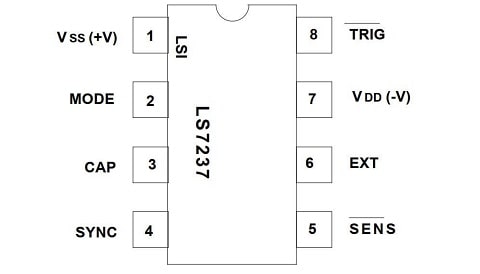
Fig. 2 – Pinout LS7237
The lamp brightness is determined by controlling the output conduction angle (Triac triggering angle) in relation to the AC line frequency.
⚠️ Caution!⚠️
This circuit works directly connected to the 110/220V electrical network, and has a high power load, any carelessness, or wrong connections, error in the project, or any other occasion, can lead to irreversible damage.
We are not responsible for any type of event. If you do not have enough experience to assemble this circuit, do not do it, and if you do, when testing, be sure to have the proper protections and be accompanied by someone else.
🤔 How the Circuit Works
The circuit works as follows: when a touch is made to the board, it causes the brightness of the lamp to change in specified steps as follows:
- LEVEL – – BRIGHTNESS(% Rated Wattage)
- Off ……………….. 0
- Night Light ……. 9
- Mood Light …… 29
- Medium ………… 66
- Maximum ……… 99
After AC power-up, the output comes up in the OFF state. Following that, every time the Touch Plate is touched, the output steps to the next level of brightness. The next step following the maximum brightness is the OFF state, initiating a new sequence.
🛠️ Features
- PLL synchronization allows use as a Wall Switch
- Provides brightness control of an incandescent lamp with a touch plate or mechanical switch
- Can control speed of shaded pole and universal AC motors
- Controls the “duty cycle” from 23% to 88% (conduction angles for AC half-cycles between 45˚ and 158˚, respectively)
- Operates at 50Hz/60Hz line frequency
- Extension input for remote activation
- +12V to +18V DC Power Supply (VSS – VDD)
- 8-Pin Plastic DIP, 8-Pin SOIC
🔌 The Schematic Circuit
The 110/220VAC 4 Step Control Touch Dimmer Switch Lamp Circuit diagram is shown in Figure 3 below.
Is a moderately simple circuit to assemble, with few external components, however one must have at least basic to advanced experience to assemble this circuit, if you are not experienced enough, ask someone more experienced to help you.
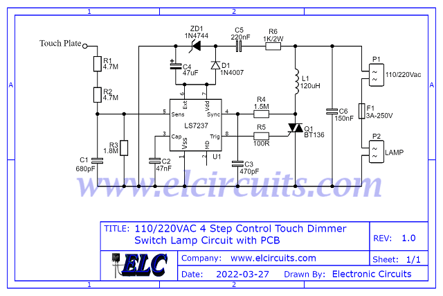
Fig. 3 – 110/220VAC 4 Step Control Touch Dimmer Switch Lamp Circuit
⚡ 110Vac or 220Vac
This circuit was designed to work with 220Vac voltage, for use in 110Vac power network, following components must be replaced in component list.
- R1, R2 …. 2.7MΩ 1/4W (red, violet, red, gold)
- R6 ……….. 270Ω 1W (red, violet, brown, gold)
- C5 ……….. 330nF / 400V polyester Capacitor
- L1 ………. 60µH (RFI Filter)
🧮 Components List
- Semiconductors
- U1 ………… LS7237 Integrated Circuit
- Q1 ………… BT136 Triac Transistor
- D1 ………… 1N4007 Diode
- DZ1 ……… 1N4744 15V/1W Zener Diode
- Resistors
- R1, R2 …. 4.7MΩ 1/4W (yellow, violet, green, gold)
- R3 ……….. 1.8MΩ 1/4W (brown, gray, green, gold)
- R4 ……….. 1.5MΩ 1/4W (brown, yellow, green, gold)
- R5 ……….. 100Ω 1/4W (brown, black, brown, gold)
- R6 ……….. 1KΩ 2W (brown, black, red, gold)
- Capacitors
- C1 ……….. 680pF / 400V Polyester Capacitor
- C2 ………… 47nF / 400V Polyester Capacitor
- C3 ……….. 470pF/ 400V Ceramic Capacitor
- C4 ……….. 47µF / 25V Electrolytic Capacitor
- C5 ……….. 220nF / 400V Polyester Capacitor
- C6 ……….. 150nF /400V polyester Capacitor
- Miscellaneous
- L1 ………. 120µH (RFI Filter)
- P1, P2 …. 2-pin PCB soldering terminal blocks
- F1 ………. 3A/250V Soldering fuse
- Others …. PCB, heat sink, power supply, wires, etc.
🖨️ Printed Circuit Board – Download
We are offering PCB – Printed Circuit Board, in GERBER, PDF and PNG files, for you who want to do most optimized assembly, either at home.
If you prefer in a company that develops board, you can be downloading and make files in Download option below.
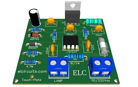
Fig. 4 – PCB 110/220VAC 4 Step Control Touch Dimmer Switch Lamp Circuit
📥 Files to Download, Direct Link:
✨ Our Gratitude and Next Steps
We sincerely hope this guide has been useful and enriching for your projects! Thank you for dedicating your time to this content.
Your Feedback is Invaluable:
Have any questions, suggestions, or corrections? Feel free to share them in the comments below! Your contribution helps us refine this content for the entire ElCircuits community.
If you found this guide helpful, spread the knowledge!
🔗 Share This Guide
Best regards,
The ElCircuits Team ⚡


