Showing posts with label Battery Charger. Show all posts

Monday, July 4, 2022

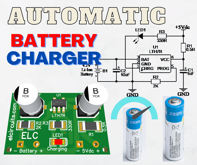
Automatic Programmable 4.2V Battery Charge, Current up to 500mA using LTH7R IC with PCB

Automatic Programmable 4.2V Battery Charge, Current up to 500mA using LTH7R IC

Effortless Battery Charging: Build an Automatic Programmable 4.2V Charger with up to 500mA Current Using LTH7R IC and PCB

The LTH7R IC is a constant current or constant voltage base charger chip, mainly used for single cell lithium battery charging.

No external sensing resistor is needed, it has its internal power MOSFET structure, so no external reverse diode is needed.

The LTH7R IC has under temperature protection and control, it adjusts the charging current automatically to limit high temperature on the chip.

Its charging voltage is fixed at 4.2V, and the charging current can be adjusted by an external resistor.
When the float voltage is reached and the charging current drops to 1/10 of the defined circuit, the LTH7R IC automatically completes the charging process.

Fig. 2 - Pinout LTH7R IC

When the input source voltage is removed, the LTH7R IC automatically enters low current mode, drawing less than 2uA from the battery.

When the LTH7R IC enters standby mode, the supply current is less than 25uA. The LTH7R IC can also monitor charging current, has the features of voltage detection, auto-cycle charging, and has an indicator pin to indicate end-of-charge status and input voltage status.

Features

  • Programmable charging current up to 500mA
  • No need for external MOSFET, sensing resistor, reverse diode
  • Constant current or constant voltage mode operation, with thermal protection function Preset charging voltage
  • Standby current is 20uA
  • 2.9V slow charge voltage
  • Soft start limits the inrush current
  • Adopt SOT23-5 package, application line

Product application

  • Microphone Battery
  • Light Camera
  • Mobile Phones, PDAs, MP3 players
  • Bluetooth headsets 

External programming of the load current:

PROG (pin 5): Constant current load current setting and load current monitoring terminal. The load current can be programmed by connecting an external resistor from the PROG pin to ground.

In the pre-charge phase, the voltage of this pin is modulated by 0.1V; in the constant current charging stage, the voltage of this pin is fixed at 1V.

In all charging state modes, measuring the voltage of this pin can estimate the charging current according to the following formula:

General Formula:

I_bat = 1000 / R_prog

To use, for example, in a charger whose required current is 300mA, we can use the formula as follows:

  • I_bat = 1000/ R_prog
  • R_prog = 1000 / I_bat
  • R_prog = 1000 / 300
  • R_Prog = 3.3K

To use, for example, in a charger whose current required is the maximum current, 500mA, we can use the formula as follows:

  • I_bat = 1000/ R_prog
  • R_prog = 1000 / I_bat
  • R_prog = 1000 / 500
  • R_Prog = 2K

We leave just below a small table ready with five models with the standard currents for the battery charger.

Model R_prog I_bat
1 10K 100mA
2 5K 200mA
3 3,3K 300mA
4 2,5K 400mA
5
2K
500mA

The Circuit Schematic

In Figure 3, below, we can see the schematic diagram of the Automatic Programmable 4.2V Battery Charge, Current up to 500mA using LTH7R IC.

All circuit components are SMD, the power supply input is done by soldering on the PCB. This type of miniaturized SMD circuit is great to be implemented in circuits with small spaces.

The capacitors are SMD electrolytic, but if you have tantalum capacitors, you can put them on, it will help with the plate height, but if you can't find them, you can use electrolytic.

The charger circuit supports voltage between 4.4V to 7V, the recommended is 5V, which is great news for us to be able to charge our battery in a PC USB port or even with cell phone chargers.

Fig. 3 - Automatic Programmable 4.2V Battery Charge, Current up to 500mA using TH7R IC

Printed Circuit Board

In Figure 4, we provide the PCB - Printed Circuit Board, in GERBER, PDF and PNG files. These files are available for free download, on the MEGA server, in a direct link, without any bypass.

All to make it easier for you to do a more optimized assembly, either at home, or with a company that prints the board. You can download the files in the Download option below.

Fig. 4 - PCB Automatic Programmable 4.2V Battery Charge, Current up to 500mA using TH7R IC

Files to download, Direct Link:

Click on the link beside: GERBER, PDF and PNG files

I hope you enjoyed it!!!

If you have any questions, suggestions or corrections, please leave them in the comments and we will answer them soon.

Subscribe to our blog!!! Click here - elcircuits.com!!!

My Best Regards!!!

Wednesday, March 16, 2022

How To Make Rechargeable Emergency LED Light Using LM350 IC with PCB

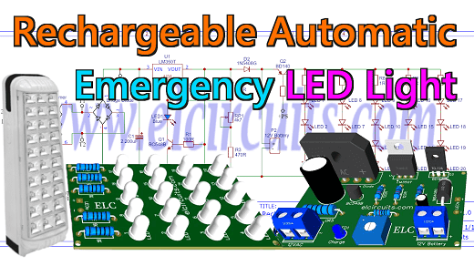
Fig. 1 - How To Make Rechargeable Emergency LED Light Using LM350 IC with PCB

Crafting a Rechargeable Emergency LED Light with LM350 IC: Step-by-Step Guide with PCB Implementation

You know that night when the power grid collapses and the power goes out, so we need a light to illuminate the darkness.

That's when we realized that we would need some equipment that could light up that darkness...

In this article, we are going to assemble a Rechargeable Automatic Emergency LED Light circuit that when the power goes out, it activates the set of LED lamps automatically using a rechargeable 12V battery.

You may be interested in: 

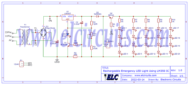
How the Circuit works

The Automatic Illuminator circuit is divided into three distinct parts:

The first part:

It's pretty obvious, we have the 220Vac or 110Vac voltage coming from the mains, and we need to convert it to 12Vac. For this, we use a 220V/12Vac transformer. The output of the 12Vac transformer, it is connected to a diode bridge to rectify the AC voltage to DC, and the 2200uF capacitor to filter this voltage.

The second part:

It is a 12V battery charging stage, it works simply as a charger, it has a status LED that when charging it stays on, and when charged the LED goes off.

The circuit uses the LM350T voltage regulator. The output current of the LM350 is 3 amps, it is necessary to adjust the output voltage through the trimpot of 4.7K, this voltage must be adjusted according to the battery used.

In some batteries this voltage is 13.8V, in others it is 14.4V, this is always described together in the general battery information.

For those who follow us here on our site, you may have already noticed that the 12V battery charger circuit is very similar to an article that we have already done here on our site, you can check it out by clicking on this link.

The Third part:

It is a control circuit composed of a BD140 PNP transistor, which works as a drive circuit, when there is power on the grid.

The voltage from the source passes through the 1K base current limiting resistor, and causes the transistor to stay open, keeping the light off, as soon as the voltage is cut off. 

The transistor as a switch closes the circuit, slinging the battery to the set of 20 LEDs, turning the light on.

The Circuit Diagram

The complete schematic diagram of the power supply is shown below in Figure 2, it is a simple but complete adjustable symmetric power supply.

Fig. 2 - Schematic Diagram Rechargeable Emergency LED Light Using LM350 IC

The Power Transformer

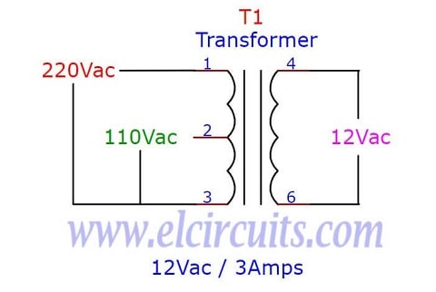
The transformer should have as primary according to your local network, 110Vac or 220Vac. The secondary should be 12V, since when we pass through the rectification, this 12Vac voltage is transformed more or less into 16.9Vdc.

The transformer should have a current of 3 amps, in case you are going to use it with large batteries, such as 7A, 9A, etc… 

If you are going to work with smaller batteries, it is up to you to place a transformer proportional to the total power of the LEDs and the battery used. The transformer configuration diagram is shown in Figure 4 below.

Fig. 3 - Schematic Diagram Transformer 110/220Vac to 12Vac 3Amps

Component List

  • Semiconductors
    • U1 ........................ LM350 Voltage Regulator  
    • Q1 ........................ BC548 NPN Transistor
    • Q2 ........................ BD140 PNP Transistor
    • D1 ........................ KBU4A - 4A Rectifier Bridge
    • D2 ........................ 1N5408 Diode Rectifier 
    • LED1 to LED20 ... Light Emitter Diode 5mm High Light
    • LED1 .................... Light Emitter Diode 3mm (general use)

  • Resistors
    • R1 ............... 100Ω 1/8w Resistor (brown, black, brown, gold
    • R2 ............... 0.5Ω 5W Resistor (green, black, silver, gold)
    • R3 ............... 470Ω 1/8w Resistor (yellow, violet, brown, gold
    • R4 ............... 120Ω 1/8w Resistor (brown, red, brown, gold
    • R5 ............... 1kΩ 1/8w Resistor (brown, black, red, gold
    • R6 to R10 ... 1Ω 3W Resistor (brown, black, black, gold)
    • RP1 ............. 4K7Ω Trimmer

  • Capacitors
    • C1 ...... 2.200uF - 25V Electrolytic capacitor 
    • C2 ...... 0.33uF - 25V Electrolytic capacitor 

  • Miscellanies
    • P1, P2 ....... Connector 2 screw terminal 5mm 2 Pins
    • T1 ............. Transformer Reduction 110/220ac to 12Vac (See Text)
    • Others ....... Wires, Solders, pcb, heat sink, etc.

PCB - Download

We provide the files with the PCB, the schematic, the PDF, GERBER and JPG, PNG and provide a direct link for free download and a direct link, "MEGA".

Fig. 4 - PCB - Rechargeable Emergency LED Light Using LM350 IC

Click on the direct link to download the files: Layout PCB, PDF, GERBER, JPG

I hope you enjoyed it!!!

If you have any questions, suggestions or corrections, please leave them in the comments and we will answer them soon.

Subscribe to our blog!!! Click here - elcircuits.com!!!

My Best Regards!!!

Monday, February 7, 2022

USB 5V 4A Car Charger using 78S05 with PCB

Fig. 1 - USB 5V 4A Car Charger using 78S05

This is a simple USB 5V 4A Car Charger circuit to charge a cell phone, tablet, or any other gadget that requires a voltage of 5V with a current of 2 Amperes via USB.

The circuit is a DC converter that takes power from a cigarette lighter socket in your vehicle, and converts the 12V battery voltage to a stabilized 5V voltage.

There are several models of USB chargers on the market, the problem is the high price, and the supply current is quite low, around 400mA to 600mA, smartphones currently have chargers with 1000mA, 1500mA, 2000mA... 

The circuit is based on the LM78S05 IC, it is extremely easy to build, using very few components. 

L78S00 Description

The L78S00 series of three-terminal positive regulators  is available in TO-220 and TO-3 package sand  with several  fixed output  voltages, making it useful in a wide range of applications. 

These regulators can provide local on card regulation, eliminating the distribution problems associated with single point regulation. Each type employs internal current limiting, thermal  shut-down and safe area protection, making it essentially indestructible. 

If adequate heat sinking is provided, they can deliver over 2A output current. Although designed primarily as fixed voltage regulators, these devices can be used with external components to obtain adjustable voltage sand currents.

Feature

  • Output Current to 2A.
  • Output  Voltage of: 5 ; 7.5 ; 9 ; 10 ; 12 ; 15 ;18 ; 24V.
  • Thermal Overload Protection.
  • Short Circuit Protection.
  • Output Transistor SOA Protection

Circuit Operation

In Figure 2, below, we can see the schematic diagram of USB 5V 4A Car Charger using 78S05, the Circuit's operation is pretty basic, what happens is that when you plug your USB converter into the cigarette socket of your car, it converts this 12V battery voltage to a regulated 5V voltage.

Fig. 2 - Schematic circuit USB 5V 4A Car Charger using 78S05

The total output current of the circuit is 4 Amps, 2A for each USB port, this is enough current to charge any USB device today.

The circuit has overload protection, which means that if there is a short circuit on the output, or if a device with higher current is connected to the USB converter, it will shut down, until that current is reduced to a maximum of 2A.

Components List

  • Semiconductors
    • U1, U2 ...... 78S05 Integrated Circuit Voltage regulator
    • LED1 ....  Light Emitter Diodo, general purpose

  • Resistor
    • R1 ..... 4.7KΩ (yellow, violet, orange, gold
    • RP1 ......... 10KΩ Trimpot
  • Capacitor
    • C1 .......... 47nF Ceramic Capacitor
    • C2 .......... 100nF Ceramic Capacitor
    • C3 .......... 4.700uF / 35V Electrolytic Capacitor 

  • Miscellaneous 
    • F1 .......... 20A - 250V soldering Fuse
    • P1 .......... 2-pin PCB soldering terminal blocks
    • P2 .......... 3-pin PCB soldering terminal blocks
    • Others .... Printed Circuit Board, heat sink, wires, etc.

Printed Circuit Board

In Figure 3, we provide the PCB - Printed Circuit Board, in GERBER, PDF and PNG files. These files are available for free download, on the MEGA server, in a direct link, without any bypass. 

All to make it easier for you to do a more optimized assembly, either at home, or with a company that prints the board. You can download the files in the Download option below.

Fig. 3 - PCB - USB 5V 4A Car Charger using 78S05

Files to Download, Direct Link:

Click on the link beside: GERBER, PDF and PNG files

If you have any questions, suggestions or corrections, please leave them in the comments and we will answer them soon.

Subscribe to our blog!!! Click Here - elcircuits.com!!!

My Best Regards!!!

Thursday, January 27, 2022

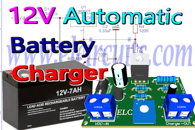
12 Volts Automatic Lead Acid Battery Charger Using LM350 IC with PCB

Fig, 1 - 12 Volts Automatic Lead Acid Battery Charger Circuit + PCB

This is a 12V Automatic Lead Acid Battery Charger Circuit, of the type used in nobreaks, with loads ranging from 1A to 9 Amps.

The main advantage of this battery charger circuit is its charging mode, since it has a charge control, so that the battery does not receive voltage when it is not needed, giving more autonomy to the battery and protecting it from overvoltage.

What is Lead Acid Battery

The lead acid battery is a type of rechargeable battery first invented in 1859 by French physicist Gaston Planté

It is the first type of rechargeable battery ever created. Compared to modern rechargeable batteries, lead-acid batteries have relatively low energy density. 

Despite this, their ability to supply high surge currents means that the cells have a relatively large power-to-weight ratio. 

These features, along with their low cost, make them attractive for use in motor vehicles to provide the high current required by starter motors.

Lead Acid Battery Charger Method

There are several features related to the charging process of various battery segments and classes. 
The charging method for lead-acid batteries differs from NiCd batteries in the voltage limit, rather than the current limit to be used.

The charging time for lead-acid (sealed) batteries is 8 to 16 hours, depending on the capacity of the battery and the method used. 

With higher charging currents and multi-stage charging methods, the charging time can be reduced to 8 hours or less. 

For a multi-stage charger, three stages of charging application are required: 
  •  Constant current
  •  Peak charge
  •  Float charge

The Circuit

In Figure 2 below, we have the schematic diagram of the lead-acid battery charger circuit. It is a very simple circuit, with few external components, easy to assemble, yet even with its simplicity it works very well.
Fig. 2 - Schematic Circuit 12 Volts Automatic Lead Acid Battery Charger Circuit

Working

The voltage regulation for charging the battery is done by the LM350 IC voltage regulator. 
The charging current control is done using the BC548B NPN transistor, it controls the demand current from the battery, causing the circuit to activate or deactivate the voltage required for charging the battery.

The potentiometer RP1 1K is used for fine tuning the battery charging voltage, which should be adjusted by using a multimeter to measure the output voltage, which should be at most 20% of the nominal battery voltage.

If you cannot find the description of the battery charging voltage on the battery itself, you can adjust the average charging voltage, which ranges from 13.8V to 14.4V.

It is necessary to use a heat sink in the voltage regulator, since the initial current to charge the battery is high. 
As the circuit charges the battery, it lowers the charging current until it reaches zero voltage, when the battery is fully charged.

Components List

  • Semiconductors
    • U1 .......... LM350 Voltage Regulator Circuit
    • Q1 .......... BC548B NPN Transistor
    • D1 .......... 1N5408 Silico Diode

  • Resistor
    • R1 .......... 100Ω Resistor (brown, black, brown, gold)
    • R2 .......... 0.5Ω 5W Resistor (green, black, silver, gold
    • R3 .......... 470Ω Resistor (yellow, violet, brown, gold)
    • R4 .......... 120Ω Resistor (brown, red, brown, gold)
    • RP1 ........ 1KΩ Potentiometer

  • Capacitor
    • C1 .......... 2.2uF / 25V Electrolytic Capacitor
    • C2 .......... 0.33uF / 25V Electrolytic Capacitor
       
  • Other
    • P1, P2 .... 2-pin PCB soldering terminal blocks
    • Others .... Printed Circuit Board, Heat Sink, tin, wires, etc.

Printed Circuit Board

In Figure 3, we provide the PCB - Printed Circuit Board, in GERBER, PDF and PNG files. These files are available for free download, on the MEGA server, in a direct link, without any bypass. 

All to make it easier for you to do a more optimized assembly, either at home, or with a company that prints the board. You can download the files in the Download option below.

Fig. 3 - PCB - 12 Volts Automatic Lead Acid Battery Charger Circuit


Files to Download, Direct Link:

Click on the link beside: GERBER, PDF and PNG files

If you have any questions, suggestions or corrections, please leave them in the comments and we will answer them soon.

Subscribe to our blog!!! Click Here - elcircuits.com!!!

My Best Regards!!!

Wednesday, January 26, 2022

Lithium (Li-Ion) Battery Charger using LP2951 IC + PCB

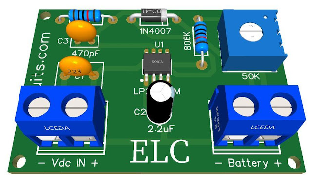
Fig. 1 - Lithium (Li-Ion) Battery Charger using LP2951 IC + PCB

Para versão em Português, Clique Aqui!

This is a complete and compact Li-Ion battery charger circuit, composed of Integrated Circuit LP2951

The circuit performs assisted and controlled charging, and this represents a longer life for your battery and a full charge giving more autonomy in the circuits powered by these batteries.

It is a very simple circuit to assemble, because the external components are minimal, due to the IC having integrated in its encapsulation all the necessary components to perform the task.

LP2951 Integrated Circuit

The LP2951 is an adjustable micro power voltage regulator suitable  for  use  in  battery-powered  systems.  

This  regulator has  various  functions  such  as  alarm  which  warns  of  a  low output voltage, often due to falling batteries on the input, the external   shutdown   which   enables   the   regulator   to   be switched on and off, current and temperature limiting.

Additional Features

The LP2951 has three additional features: 

  • 1st - Error output that can be used to signal external circuits of an out-of-regulation condition or as a microprocessor reset trigger. 
  • 2nd - Allows the output voltage to be preset to 5.0 V, 3.3 V or 3.0 V (depending on the version) or programmed from 1.25 V to 29 V. It consists of a fixed resistor divider along with direct access to the Error input on the internal operational amplifier feedback. 
  • 3rd - It has a shutdown input that allows a logic level signal to turn the regulator output off or on.

What it is used for

Due to the low specifications for input to output voltage differential and bias current, this device is ideal for computers, consumers, and battery powered industrial equipment where extended battery life is desirable, battery charger. 

The LP2951 is available in eight-pin dual-line, SOIC-8 and Micro-8 surface mount packages. Devices with an 'A' suffix have an initial output voltage tolerance of ± 0.5%.

Features

  • Low Quiescent Current 
  • Low Dropout Voltage
  • Low Temperature Coefficient
  • Tight Line and Load Regulation
  • Guaranteed 100mA Output Current
  • Internal Short Current & Thermal Limit
  • Error Signals of Output Dropout (8 pin Versions only)
  • External Shut Down ( 8-Pin Versions Only)

The Circuit

In Figure 2 below we can see the schematic diagram of the Li-Ion battery charger, the LP2951 IC is responsible for measuring the state of the battery through the voltage divider, at the charging voltage output of the battery, and thereby control it to not emit an unnecessary charge.
Fig. 2 - Schematic Diagram Lithium (Li-Ion) Battery Charger using LP2951 IC


Capacitor C1 and C2 act as an RF filter to eliminate spurious, capacitor C3 is for stability of the feedback system, the 50K potentiometer RP1 is to adjust the system according to the operating voltage of the cell.

The Li-Ion battery charger circuit can be powered by a DC voltage between 6 to 10V with a current equal to 1.5 times the capacity of the cells to be charged.

Charger Operation

When we connect the power supply to the circuit and insert the battery, the LP2951 IC checks the charging status and, when it detects a charge below the programmed one, it triggers the charging to complete the charge.

After the battery is fully charged, the circuit goes into sleep mode, it keeps checking periodically the status of the battery and if necessary it activates the continuity of charging. 

Components List

  • Semiconductors
    • U1 .......... LP2951 Voltage Regulator Circuit
    • D1 .......... 1N4007 Silico Diode

  • Resistor
    • R1 .......... 2MΩ 1%  Precision Resistor (red, black, yellow, brown)
    • R2 .......... 806KΩ 1%  Resistor (gray, black, blue, orange, brown
    • RP1 ........ 50KΩ Potentiometer

  • Capacitor
    • C1 .......... 0.1uF or 100nF Polyester/Ceramic Capacitor
    • C2 .......... 2.2uF / 16V Electrolytic Capacitor
    • C3 .......... 470pF Polyester/Ceramic Capacitor
       
  • Other
    • B1, B2 ... 2-pin PCB soldering terminal blocks
    • Others .... Printed Circuit Board, tin, wires, etc.

Printed Circuit Board

In Figure 3, we provide the PCB - Printed Circuit Board, in GERBER, PDF and PNG files. These files are available for free download, on the MEGA server, in a direct link, without any bypass. 

All to make it easier for you to do a more optimized assembly, either at home, or with a company that prints the board. You can download the files in the Download option below.

Fig. 3 - PCB - Lithium (Li-Ion) Battery Charger using LP2951 IC

Files to Download, Direct Link:

Click on the link beside: GERBER, PDF and PNG files

If you have any questions, suggestions or corrections, please leave them in the comments and we will answer them soon.

Subscribe to our blog!!! Click Here - elcircuits.com!!!

My Best Regards!!!