 Português
 Español
FM Transmitter 70–150 MHz with MAX2606 IC + PCB
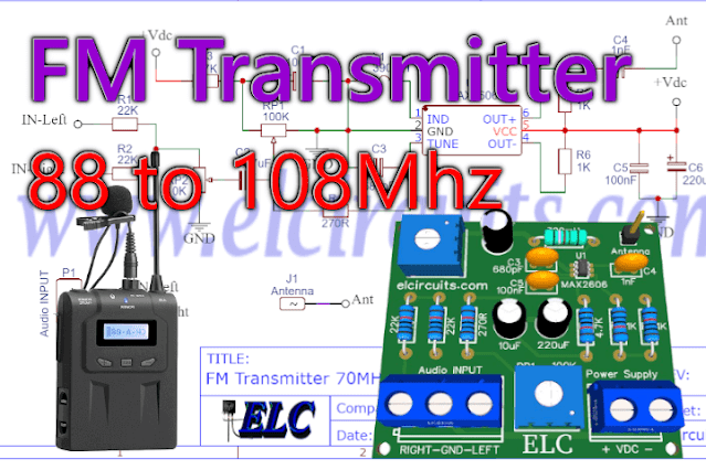
Fig. 1 – FM Transmitter 70MHz to 150MHz using MAX2606 IC with PCB
This is a low power micro FM transmitter with a voltage controlled oscillator, VCO, that covers the FM Modulated Frequency bands from 88 to 108Mhz, adjusted by a trimpot.
The transmitter is based on the MAX2606 integrated circuit, which brings us great advantages, and one of the main ones is that the transmitter has a very small size, and can also be used for “Espionage”.
The MAX2606 Integrated Circuit
The MAX2606 is a compact high-performance intermediate-frequency (IF) Voltage Controlled Oscillators (VCOs) designed specifically for demanding portable wireless communication systems.
They combine monolithic construction with low-noise, low-power operation in a tiny 6-pin SOT23 package, as showed in Figure 2 above.

Fig. 2 – Pinout MAX2606 Integrated Circuit
These low-noise VCOs feature an on-chip varactor and feedback capacitors that eliminate the need for external tuning elements, making the MAX2605–MAX2609 ideal for portable systems.
Only an external inductor is required to set the oscillation frequency. In addition, an integrated differential output buffer is provided for driving a mixer or pre-scaler.
The buffer output is capable of supplying up to -8dBm (differential) with a simple power match. It also provides isolation from load impedance variations.
The MAX2606 operate from a single +2.7V to +5.5V power supply and offer low current consumption. These IF oscillators can cover the 70MHz to 150MHz frequency range.
Features
- Small Size
- Integrated Varactor for Tuning
- Low Phase Noise
- Wide Application Frequency Range
- Differential or Single-Ended Outputs
- Single +2.7V to +5.5V Supply
- Ultra-Small SOT23-6 Package
- On-Chip Temperature-Stable Bias
- Low-Current Operation
ATTENTION!
For each Country, Region, State… There are Laws on broadcasting, telecommunications, audio and video transmission, etc.
Do not use telecommunications equipment without authorization from the entities responsible for transmitting Radio Frequencies.
Electronic Circuits teaches electronics applied to various segments, with the aim of improving knowledge, we do not support or take responsibility for any type of illegal operation.
For any operation with RF, we recommend looking for the competent regulatory agencies, seeking certification and/or legalization.
You might also be interested in:
- FM Transmitter 75 to 108MHz using BA1404 IC with PCB
- 2.5KM FM transmitter, using transistor 2N3866 with PCB
Transmitter Operation
This FM Transmitter circuit has its frequency adjustment through a Varicap diode built in the MAX2606 chip, this means that the frequency oscillator of the transmitter is controlled by applying voltage to input pin 3 of the MAX2606 chip.
The Frequency
The nominal frequency of the transmitter using the MAX2606 is 70 to 150 MHz, however, for our project we used a 390uH coil, which sets the frequency of the transmitter oscillator to the range 88 to 108 MHz.
Audio Input
The audio input is balanced through two resistors R1 and R2, so we can work with stereo input.
The RP2 Trimpot controls the gain of the transmitter’s audio input, remembering that the audio input signal should not exceed 60mV to avoid distortions.
Frequency Adjustment
The RP1 Trimpot controls the oscillation frequency of the transmitter, varying the commercial FM frequency range from 88 to 108 MHz.
The antenna consists of a piece of wire approximately 75 cm long.
The coil L1 is 390mH, in case you cannot get a commercial coil, you can build one with approximately 8 to 14 turns of 0.5mm diameter copper wire wrapped around a 5mm core.
To make a finer adjustment, you can be compressing or expanding the coil, and thus change its inductance.
The Power Supply
The MAX2606 integrated circuit works with a supply voltage ranging from 2.7 to 5.5Vdc with a current of 2.1mA. If you are going to use a power supply it is recommended to have good filtering, since Radio Frequency Transmitters are very sensitive to interference.
But, as most already intend to do with batteries, it is recommended not to use long wires, so as not to pick up external electromagnetic interference.
The Circuit
In Figure 2 below we can see the schematic diagram of FM Transmitter 70MHz to 150MHz using MAX2606 IC.
It is a circuit that has moderate difficulty, and should be assembled by people who have at least an intermediate level of knowledge.
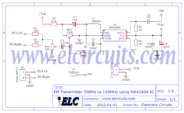
Fig. 3 – Schematic Circuit FM Transmitter 70MHz to 150MHz using MAX2606 IC
Components List
- Semiconductors
- U1 ………. MAX2606 Integrated Circuit
- Resistor
- R1, R2 ….. 22KΩ (red, red, orange, gold)
- R3 ………… 4.7KΩ (yellow, violet, red, gold)
- R4 ………… 270Ω (red, violet, brown, gold)
- R5, R6 ….. 1KΩ (brown, black, red, gold)
- RP1 ……… 100KΩ Trimpot
- RP2 ……… 10KΩ Trimpot
- Capacitor
- C1 ………. 10uF / 16V Electrolytic Capacitor
- C2 ………. 0.47uF / 16V Electrolytic Capacitor
- C3 ………. 680pF Ceramic Capacitor
- C4 ………. 1nF Ceramic Capacitor
- C5 ………. 100nF Polyester/Ceramic Capacitor
- C6 ………. 220uF / 16V Electrolytic Capacitor
- Miscellaneous
- P1 ………. 3-pin PCB soldering terminal blocks
- P2 ………. 2-pin PCB soldering terminal blocks
- Others …. Printed Circuit Board, tin, wires, etc.
Printed Circuit Board
In Figure 3, we provide the PCB – Printed Circuit Board, in GERBER, PDF and PNG files. These files are available for free download, on the MEGA server, in a direct link, without any bypass.
All to make it easier for you to do a more optimized assembly, either at home, or with a company that prints the board. You can download the files in the Download option below.
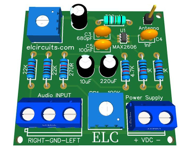
Fig. 3 – PCB – FM Transmitter 70MHz to 150MHz using MAX2606 IC
Files to Download, Direct Link:
Click on the link beside: GERBER, PDF and PNG files
✨ Our Gratitude and Next Steps
We sincerely hope this guide has been useful and enriching for your projects! Thank you for dedicating your time to this content.
Your Feedback is Invaluable:
Have any questions, suggestions, or corrections? Feel free to share them in the comments below! Your contribution helps us refine this content for the entire ElCircuits community.
If you found this guide helpful, spread the knowledge!
🔗 Share This Guide
Best regards,
The ElCircuits Team ⚡


