 Português
 Español
12V to 220V 500W Inverter 60Hz with IR2153D IC + PCB

You know that moment when you are at home tired from work, ready for bed, and suddenly the power goes out? Yes my friends, it is a moment that we don’t want to happen, but we know it happens.
The best thing in these moments is to have something that can supply our power outage problem… With this we present a simple circuit, easy to build and very cheap.
I present to you a simple circuit to build, whose purpose is precisely to provide AC power to feed a fan, the lights, and some electronic equipment, with a 12V battery.
Integrated Circuit IR2153D
The IR2153D is an improved version of the popular IR2155 and IR2151 gate driver ICs, and incorporates a high voltage half-bridge gate driver with a front end oscillator similar to the industry standard CMOS 555 timer.
The IR2153D provides more functionality and is easier to use than previous ICs. A shutdown feature has been designed into the CT pin, so that both gate driver outputs can be disabled using a low voltage control signal.
In addition, the gate driver output pulse widths are the same once the rising under voltage lock out threshold on VCC has been reached, resulting in a more stable profile of frequency vs time at startup.
Noise immunity has been improved significantly, both by lowering the peak di/dt of the gate drivers, and by increasing the under-voltage lockout hysteresis to 1V.
Finally, special attention has been payed to maximizing the latch immunity of the device, and providing comprehensive ESD protection on all pins.
Features
- Integrated 600V half-bridge gate driver
- 15.6V zener clamp on Vcc
- True micropower start up
- Tighter initial deadtime control
- Low temperature coefficient deadtime
- Shutdown feature (1/6th Vcc) on CT pin
- Increased under-voltage lockout Hysteresis (1V)
- Lower power level-shifting circuit
- Constant LO, HO pulse widths at startup
- Lower di/dt gate driver for better noise immunity
- Low side output in phase with RT
- Internal 50nsec (typ.) bootstrap diode (IR2153D)
- Excellent latch immunity on all inputs and outputs
- ESD protection on all leads
- Also available LEAD-FREE
Circuit Works
In Figure 2, below, we can see the schematic diagram of 12V to 220V 600Hz 500W inverter, the circuit works in a simple and direct way, when feeding the circuit the IR2153D IC starts operating, and triggers a square wave in the GATEs of the output MOSFETs transistors.

Fig. 2 – Schematic Circuit 12V to 220V 60Hz 500W Inverter using IR2153D with PCB
This triggering is done by cycle, when triggering the HO output, pin 7 is at HIGH, and the MOSFETs are activated, in the next cycle the work, the HO output is turned off, and the LO output is activated, that is, pin 5 is set to HIGH, and this cycle repeats.
This causes an oscillation in the secondary of the transformer, generating a magnetic field that will be passed to the primary of the transformer, which is the output, thus generating an output voltage of 110V or b at a frequency of 50Hz or 60Hz, this frequency is adjusted in the trimpot.
Transformer
The transformer is a network transformer with secondary windings with 10V center tape, and should have a power according to the consumption power, or load that you will use.
Power Supply – Safety Voltage
The power supply must have enough current to provide the circuit’s consumption demand. The supply voltage should be in the 9 – 14V range.
If the supply voltage drops too low and falls below 9V, the IR2153D circuit will shut down, preventing damage to the battery or battery bank, or to the inverter circuit.
Efficiency and Consumption
The battery, or batteries bank, must provide a sufficiently high current, according to the consumption of your device, for example, for a 100W consumption of the inverter, you should take into account a battery that supplies this power.
Considering that the average efficiency factor of this equipment is approximately 80%, we will consider that for an average consumption of 100W, we will use a basic account for this:
Power in W of the load * 1.2 (20% efficiency loss) = Power in W of the Inverter
So:
100W of the load x 1.2 = 120W total
So let us now use ohms law to formulate our account:
- General formula:
- P = V * I
A consumption of 120W with a battery voltage of 12V, we would be left with:
- I = P / V
- I = 120 / 12
- I = 10A
For a 100W load we would have a consumption of 10A per hour.
Components List
- Semiconductors
- U1 ………. IR2153D Integrated Circuit
- Q1 to Q6 …. IRF3205 N-Channel Power Mosfet
- Resistor
- R1 ……….. 47KΩ (yellow, violet, orange, gold)
- RP1 ……… 10KΩ Trimpot
- Capacitor
- C1 ………. 47nF Ceramic Capacitor
- C2 ………. 100nF Ceramic Capacitor
- C3 ………. 4.700uF / 35V Electrolytic Capacitor
- Miscellaneous
- F1 ………. 20A – 250V soldering Fuse
- P1 ………. 2-pin PCB soldering terminal blocks
- P2 ………. 3-pin PCB soldering terminal blocks
- Others …. Printed Circuit Board, heat sink, wires, etc.
Printed Circuit Board
In Figure 3, we provide the PCB – Printed Circuit Board, in GERBER, PDF and PNG files. These files are available for free download, on the MEGA server, in a direct link, without any bypass.
All to make it easier for you to do a more optimized assembly, either at home, or with a company that prints the board. You can download the files in the Download option below.
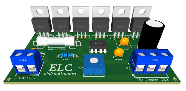
Fig. 3 – PCB – 12V to 220V 60Hz 500W Inverter using IR2153D
Files to Download, Direct Link:
Click on the link beside: GERBER, PDF and PNG files
✨ Our Gratitude and Next Steps
We sincerely hope this guide has been useful and enriching for your
projects! Thank you for dedicating your time to this content.
Your Feedback is Invaluable:
Have any questions, suggestions, or corrections? Feel free to share them
in the comments below! Your contribution helps us refine this
content for the entire ElCircuits community.
If you found this guide helpful, spread the knowledge!
Best regards,
The ElCircuits Team ⚡


