 Português
 Español
200W RMS Stereo Amplifier using STK4231II IC + PCB

PCB 200W RMS Stereo Power Amplifier IC STK4231II
For Portuguese version, click here!
This audio amplifier circuit is a HI-FI two-channel 100w OCL High Power Stereo Audio Amplifier based on the STK4231II IC.
STK4231 is a Thick film hybrid IC two-channel 100W min AF Power Amp, manufactured by SANYO ELECTRIC CO. LTD JAPAN. The STK4221II IC is a dual high power amplifier chip, preferably suited for compact high power audio applications, it provides 2 channel high power best quality audio output of 100W RMS at both channel at 8Ω speaker.
You might also be interested in:
- 170W AB Class Bridge Mode Amplifier using TDA7294 IC + PCB
- High Fidelity 14W – 12V Power Amplifier using TDA2030 IC + PCB
- 24W Stereo Hi-Fi Audio Amplifier using TDA2616 + PCB
- HI-FI 120W RMS Amplifier Circuit using LM4780 IC + PCB
- 4 x 50W High Power Amplifier, 14.4V – IC TDA7563A + PCB
- 180W RMS 4-Channel Amplifier with TDA7386 + PCB
- 320W Power Audio Amplifier, Powered with 14.4V – 2Ω with IC TDA7560 + PCB
- 100W RMS Audio Amplifier IC TDA7294 + PCB
Features
The STK4201II series are pin-compatible in the range output of 60W to 100W, are 22 pin SIP (Single Inline Package) IC with a special case designing for operation at more heat dissipation to generally reduce external heat sink.
But use a heat sink for protection. This IC is generally used in the home microsystem, car audio. The real IC image is shown below in Figure 2.

Fig. 2 – Pinout of IC STK4231II
Figure 3 below, show the schematic circuit diagram 100W + 100W RMS Stereo Power Audio Amplifier to be followed, with the arrangement of the components and their configurations.
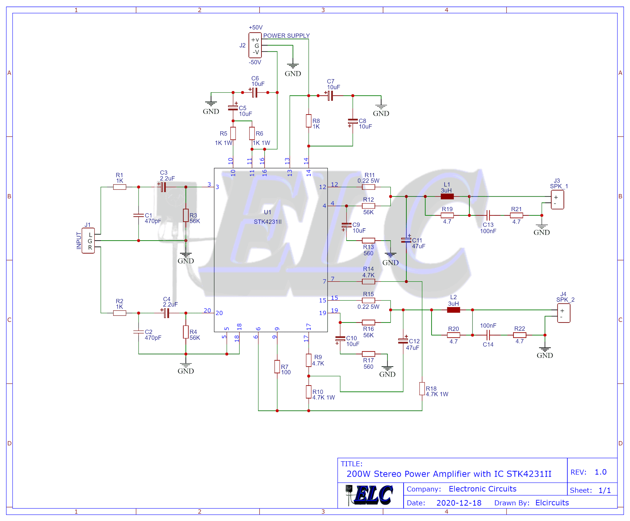
Fig. 3 – Schematic 200W Stereo power amplifier IC STK4231II
Components List
- U1…………………………… STK4231II – Audio Amplifier Integrated Circuit
- R1, R2, R8 ………………. 1K ohms – 1/8 W – brown, black, red
- R3, R4, R12, R16 …….. 56K ohms – 1/8 W – green, blue, orange
- R5, R6 …………………….. 1K ohms – 1W – brown, black, red
- R7 …………………………… 100 ohms – 1/8 W – brown, brown, black
- R9, R14 …………………… 4.7K ohms – 1/8 W – yellow, violet, red
- R10, R18 …………………. 4.7K ohms – 1W – yellow, violet, red
- R11, R15 …………………. 0.22 ohms – 5W – red, red, silver, gold , black
- R13, R17 …………………. 560 ohms – 1/8 W – green, blue, brown
- R19, R20, R21, R22 ….. 4.7 ohms – 18W – yellow, violet, gold
- R10 …………………………. 4.7K ohms – 1W – yellow, violet, red
- C1, C2 ………………………… 470pF – Polyester or Ceramic Capacitor
- C3, C4 ………………………… 2.2uF – Electrolytic Capacitor
- C5, C6, C7, C8, 9, C10 …. 10uF – 63V – Electrolytic Capacitor
- C11, C12 …………………….. 47 uF – 63V – Electrolytic Capacitor
- C13, C14 ……………………. 100 nF – Polyester or Ceramic Capacitor
- L1, L2 ………………………… 3uH inductor
- J1, J2 ………………………….. Kre Block Terminal Terminal 3-Way Triple Connector
- J1, J2 ………………………….. Kre Block Terminal Terminal 2-Way Double Connector
- Others ………………………… Printed Circuit Board, tin, wire, etc.
Specified Transformer Power Supply
The power transformer must have a Dual Supply Capacity and 5 Amperes minimal current, this circuit is powered by a constant-voltage Dual Power Supply (+50V, 0V, -50V) CC, for the correct operation.
The power supply is the same as the one in Figure 4, available on the FVML website which is our partner,the difference is that the transformer is 35V AC, which after filtering will be approximately 50V DC.
Clicking in image below, you will be directed to the FVML website, which even has the calculations to understand it better and the printed circuit board files with GERBER files to download.
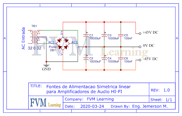
Fig. 4 Schematic Power Supply, click to download free the Gerber files
We are offering to download the link with the printed circuit board printing files, they are; Gerber, PDF layout, PNG, all the files with a direct link to Mega.
Direct link to download
Click in the link below to download the Files: PCB Layout, PDF, GERBER
✨ Our Gratitude and Next Steps
We sincerely hope this guide has been useful and enriching for your projects! Thank you for dedicating your time to this content.
Your Feedback is Invaluable:
Have any questions, suggestions, or corrections? Feel free to share them in the comments below! Your contribution helps us refine this content for the entire ElCircuits community.
If you found this guide helpful, spread the knowledge!
🔗 Share This Guide
Best regards,
The ElCircuits Team ⚡


