 Português
 Español
24W Stereo Hi-Fi Audio Amplifier using TDA2616 IC + PCB
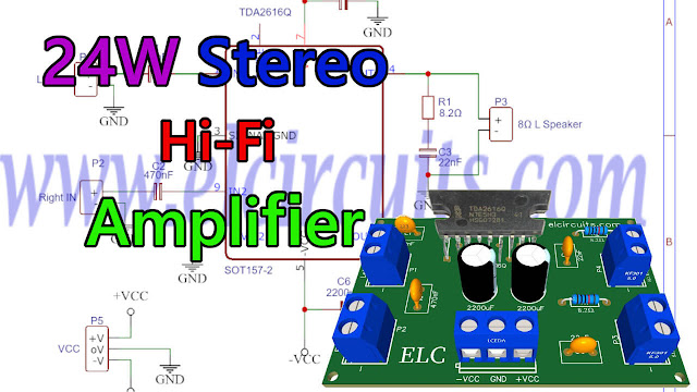
24W Stereo Hi-Fi Audio Amplifier using TDA2616 + PCB
In this article, we show you how to build a simple and portable 12W + 12W audio amplifier using the TDA2616 Integrated Circuit.
The TDA2616 IC is a stereo power audio amplifier, it comes with plastic package (SOT131) single-in-line 9-lead (SIL9).
This IC is explicitly designed for mains powered amplifier circuits, such as stereo radio, instrument return box, TV sets and so on.
The TDA2616 IC has a good input gain balance on both channels in accordance with IEC 268 and DIN 45500 standards.
In addition, the TDA2616 has a special integrated circuit for the suppression of noise signals at the inputs during activation and deactivation, which avoids clicking sounds or the famous popping during circuit operation.
You might also be interested in:
- 170W AB Class Bridge Mode Amplifier using TDA7294 IC + PCB
- High Fidelity 14W – 12V Power Amplifier using TDA2030 IC + PCB
- 4 x 50W High Power Amplifier, 14.4V – IC TDA7563A + PCB
- 100W RMS Audio Amplifier IC TDA7294 + PCB
- HI-FI 120W RMS Amplifier Circuit using LM4780 IC + PCB
- 180W RMS 4-Channel Amplifier with TDA7386 + PCB
- 200W RMS Stereo Power Amplifier with IC STK4231II + PCB
- 320W Power Audio Amplifier, Powered with 14.4V – 2Ω with IC TDA7560 + PCB
Features
- Requires very few external components
- No switch-on/switch-off clicks
- Input mute during switch-on and switch-off
- Low offset voltage between output and ground
- Excellent gain balance of both amplifiers
- Hi-fi in accordance with IEC 268 and DIN 45500
- Short-circuit proof and thermal protected
- Mute possibility.
In Figure 2 below, we show the complete 24W Stereo Audio Amplifier Circuit using TDA2616 IC, as we can see, there are few external components, which makes it easier for those who do not have much experience with assembling electronic circuits.
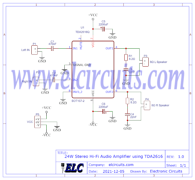
Fig. 2 – Schematic 24W Stereo Hi-Fi Audio Amplifier with Mute using TDA2616
Amplifier Operation
This amplifier circuit was designed to work with a symmetrical power supply, maximum power supply voltage is 21V, however recommended is 16V, with this voltage, an output power of 2 × 12 W is obtained (with THD = 0 .5%) with a load of 8Ω.
The mute circuit can also be activated via pin 2. When a current of 300µA is present at pin 2, circuit is in the mute condition.
The internal gain voltage is fixed at 30dB, which allows us a stable balance between the two amplifier channels (0.2dB).
Components List
- U1 ………………….. TDA2616 Integrated circuit
- R1, R2 ……………. 8.2Ω resistor (brown, black, orange, gold)
- C1, C2 ……………. 470nF ceramic, polyester capacitor
- C3, C4 ……………. 22nF ceramic, polyester capacitor
- C5, C6 ……………. 2200uF / 25V electrolytic capacitor
- P1, P2, P3, P4 …. Screw Terminal Type 5mm 2-Pin Connector
- P5 ………………….. Screw Terminal Type 5mm 3-Pin Connector
- Others ……………. PCB, tin, wires, soldering Iron, etc.
Download
We provide files with the PCB, schematic, PDF, GERBER and JPG, PNG and provide a direct link for free download and a direct link, “MEGA“.
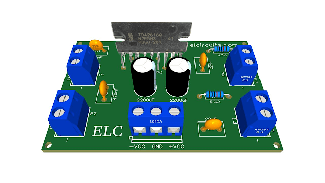
Fig. 3 – PCB – 3D – 24W Stereo Hi-Fi Audio Amplifier with Mute using TDA2616
Click on the direct link to download the files: Layout PCB, PDF, GERBER, JPG
✨ Our Gratitude and Next Steps
We sincerely hope this guide has been useful and enriching for your projects! Thank you for dedicating your time to this content.
Your Feedback is Invaluable:
Have any questions, suggestions, or corrections? Feel free to share them in the comments below! Your contribution helps us refine this content for the entire ElCircuits community.
If you found this guide helpful, spread the knowledge!
🔗 Share This Guide
Best regards,
The ElCircuits Team ⚡


