 Português
 Español
Smart Li-Ion Battery Charger Circuit using LP2951 IC + PCB

Lithium (Li-Ion) Battery Charger using LP2951 IC + PCB
Hello, electronics enthusiasts!
In today’s post, we will build a lithium-ion (Li-Ion) battery charger. The circuit performs controlled charging, which represents a longer lifespan for your battery and a full charge giving more autonomy to the batteries.
All of this in a simple way, as the external components are minimal, due to the IC having integrated in its package all the necessary components to perform the task.
🧩 The Integrated Circuit
The LP2951 is a low dropout voltage regulator designed specifically to maintain proper regulation with an extremely low voltage differential between input and output.
This device features a low quiescent bias current of 75µA, and is capable of delivering output current greater than 100mA. It also provides internal protection against overcurrent and thermal limiting.
🔬 Additional Features
The LP2951 has three additional features. The first is the Error Output that can be used to signal external circuits of an out-of-regulation condition or as a microprocessor reset activator.
The second feature allows the output voltage to be preset to 5.0 V, 3.3 V or 3.0 V (depending on the version) or programmed from 1.25 V to 29 V. It consists of a fixed resistor divider along with direct access to the Error Input in the internal operational amplifier feedback.
The third feature is a shutdown input that allows a logic level signal to turn off or on the regulator output.
Due to the low input-to-output voltage dropout specifications and bias current, this device is ideal for battery-powered computers, consumer and industrial equipment where battery life extension is desirable.
The LP2951 is available in eight-pin surface mount packages, SOIC-8 and Micro8. Devices with the ‘A‘ suffix feature an initial output voltage tolerance of ± 0.5%.
#️⃣ Features
- Available in Pb-Free package
- Low quiescent bias current 75 uA
- Low input-to-output voltage dropout of 50 mV at 100 uA and 380 mV at 100 mA
- Output of 5.0 V, 3.3 V or 3.0 V ± 0.5% allows use as regulator or reference
- Extremely tight line and load regulation
- Requires only a 1.0 uF output capacitor for stability
- Internal current and thermal limit
- NCV prefix for automotive and other applications requiring site and control changes
- Error output signals an out-of-regulation condition
- Programmable output from 1.25 V to 29 V
- Logic level shutdown input
🔌Schematic Diagram of the Charger Circuit
In Figure 2 below we can see the schematic diagram of the Li-Ion battery charger, and the LP2951 IC is responsible for measuring the battery status through the voltage divider at the battery charging voltage output, and with this, control it to not emit unnecessary charge.
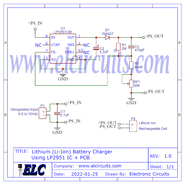
Fig. 2 – Schematic Diagram Lithium (Li-Ion) Battery Charger using LP2951 IC
The capacitor C1 and C4 serves as an RF filter for parasitic spurious signals, and the capacitor C2 is for the stability of the Feedback feedback system, the 50K potentiometer P1 is to adjust the system according to the operating voltage of the cell.
The Lithium-Ion battery charger circuit can be powered by a DC voltage between 6 to 10V with a current equal to 1.5 times the capacity of the cells to be charged.
📚 You may be interested in:
- 3.7V Li-Ion Battery Charger Circuit using MCP73831 IC + PCB
- Simple 12V battery charger with automatic charging indicator + PCB
- 12 Volts Automatic Lead Acid Battery Charger Using LM350 IC with PCB
- How To Make Rechargeable Emergency LED Light Using LM350 IC with PCB
- USB 5V 4A Car Charger using 78S05 with PCB
🪫 Operation
When we connect the power supply to the circuit and insert the battery, the LP2951 IC checks the charging status and, when it detects a charge below the programmed level, it activates charging to complete the charge.
After the battery is fully charged, the circuit enters standby mode, it keeps checking the battery status periodically and if necessary it activates the continuation of charging.
🧾 Bill of Materials
- Semiconductors
- U1 ………. LP2951 (SOT-8) SMD Voltage Regulator Circuit
- D1 ………. 1N4007 Silico Diode
- Resistor
- R1 ………. 2MΩ 1% Precision Resistor (red, black, yellow, brown)
- R2 ………. 806KΩ 1% Resistor (gray, black, blue, orange, brown)
- RP1 …….. 50KΩ Potentiometer
- Capacitor
- C1 ………. 0.1uF or 100nF Polyester/Ceramic Capacitor
- C2 ………. 2.2uF / 16V Electrolytic Capacitor
- C3 ………. 470pF Polyester/Ceramic Capacitor
- Other
- Others …. Printed Circuit Board, tin, wires, etc.
🖨️ The Printed Circuit Board (PCB)
In Figure 3, we provide the PCB – Printed Circuit Board, in GERBER, PDF and PNG files. These files are available for free download, on the MEGA server, in a direct link, without any bypass.
All to make it easier for you to do a more optimized assembly, either at home, or with a company that prints the board. You can download the files in the Download option below.

Fig. 3 – PCB – Lithium (Li-Ion) Battery Charger using LP2951 IC
📥 Files to Download, Direct Link:
To download the necessary files for assembling the electronic circuit, simply click on the direct link provided below:
Click on the link beside: GERBER, PDF and PNG files
✨ Our Gratitude and Next Steps
We sincerely hope this guide has been useful and enriching for your projects! Thank you for dedicating your time to this content.
Your Feedback is Invaluable:
Have any questions, suggestions, or corrections? Feel free to share them in the comments below! Your contribution helps us refine this content for the entire ElCircuits community.
If you found this guide helpful, spread the knowledge!
🔗 Share This Guide
Best regards,
The ElCircuits Team ⚡


