 Português
 Español
13.8V 10A Stabilized Power Supply Circuit with PCB
Stabilized Power Supply 13.8V High Current 10 Amps
This is an excellent and simple stabilized power supply of 13.8V and high current, 10 Amps. This power supply has great stability, and you can use it with a large number of projects, such as:
- Power supply for Radio Amateurs: Which need a high current and excellent stabilization to work
- Batteries chargers: Since, 13.8V is a good voltage to charge most batteries, automotive sound power supply, etc.
Finally, it can be used for countless types of projects, not to mention that its assembly is easy to build, using discrete components that are easy to acquire.
🔌PS Schematic Diagram
In the Figure 2 below, show the schematic diagram to be followed, with the arrangement of the components and their configurations.
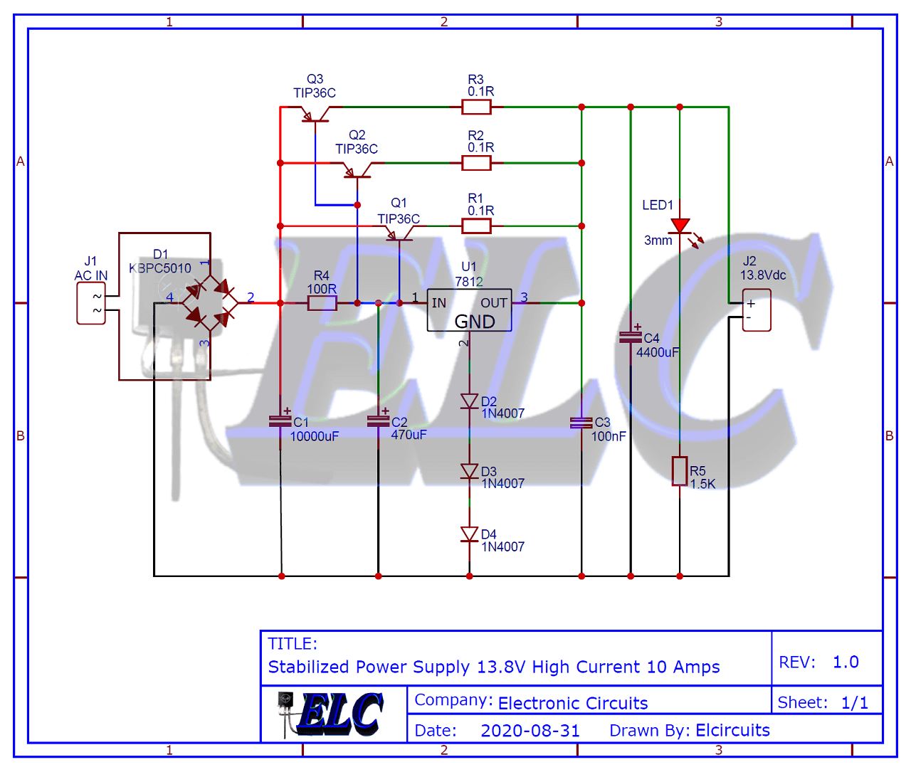
Fig 2 – Stabilized Power Supply 13.8V High Current 10 Amps
You may be interested in:
- Switched Power Supply SMPS 13.8V 10A using IR2153 IC and IRF840, with PCB
- Adjustable Power Supply 1.5V to 28V, 7.5A With IC LT1083 + PCB
- Adjustable Switching Power Supply 5.1 to 40V, 2.5 Amp using L4960 + PCB
- Adjustable Power Supply 1.2V to 37V, 6A, Short Circuit Protection with LM317 and TIP36 + PCB
- Symmetrical Adjustable Power Supply 1.25V to 47V 10 Amps with Short Circuit Protection + PCB
- Adjustable Power Supply 1.2 to 37V High Current 20A with LM317 and TIP35C + PCB
- Adjustable Power Supply 1.25v to 57V, 6 Amps with TIP36C + LM317HV + PCB
- Adjustable Power Supply 1.25v to 33V, 3 Amps with LM350 + PCB
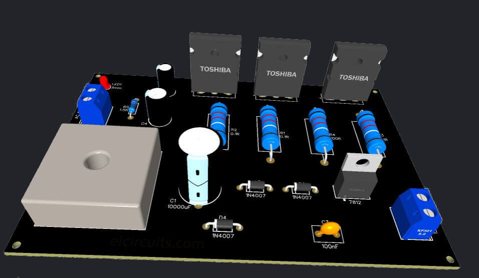
🧾 Complete Bill of Materials
- U1 ………………… Linear Voltage Regulator LM7812
- Q1, Q2, Q3 ………. PNP TIP36C Power Transistor
- D1 ………………… Bridge Rectifier – KBPC5010 – 100V, 50A
- D2, D3, D4 ………. Silicon Diodes 1N4007
- LED1 …………….. Light Emitting Diode – LED 3mm or 5mm “General purpose”
- R1, R2, R3 ………. Power Resistor 0.1Ω 5W (brown, black, silver, gold)
- R4 ………………… Resistor 100Ω 3W (brown, black, brown)
- R5 ………………… Resistor 1.5KΩ 1/4W (brown, red, red)
- C1 ………………… Electrolytic Capacitor 10.000µF /35V
- C2 ………………… Electrolytic Capacitor 470µF /35V
- C3 ………………… Polyester/Ceramic Capacitor 0.1µF or 100nF
- C4 ………………… Electrolytic Capacitor 4400µF /35V
- J1, J2 ……………… Kre Block Terminal Terminal 2-Way Double Connector
- Miscellaneous …….. Printed Circuit Board, tin, wire, etc.
🌀 The Transformer
The power transformer must have a supply capacity of at least 10 Amperes, this taking into account that you want to use this circuit for 10A.
You may be using a power transformer with a smaller capacity that will not harm the circuit, just making it clear, that if a power transformer with a lower current is placed, for example, 5A, at the output you will have a maximum of 5A.
I said at most because, we know that there are losses due to dissipation, conversion, etc., but it’ll work, the voltage of the transformer must be at least 12Vac, and a maximum of 18Vac, for a more efficient operation.
🖨️ Printed Circuit Board (PCB) – Download
We are making the PCI available in GERBER, PDF and JPEG files, for those who want to create a more optimized assembly, either at home, or if you prefer, at a company that prints the board.
📥 Files to Download, Direct Link:
Click on the link beside: PCB Layout, PDF, GERBER
✨ Our Gratitude and Next Steps
We sincerely hope this guide has been useful and enriching for your projects! Thank you for dedicating your time to this content.
Your Feedback is Invaluable:
Have any questions, suggestions, or corrections? Feel free to share them in the comments below! Your contribution helps us refine this content for the entire ElCircuits community.
If you found this guide helpful, spread the knowledge!
🔗 Share This Guide
Best regards,
The ElCircuits Team ⚡


