 |
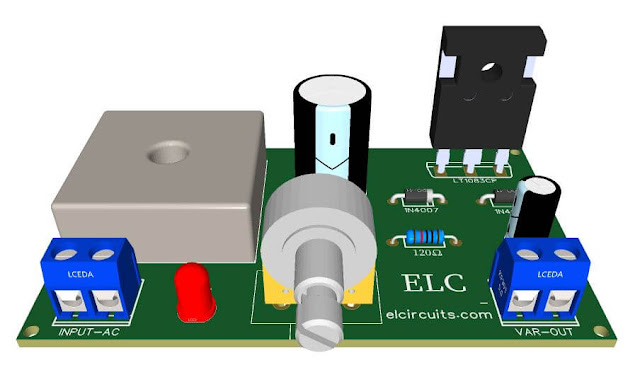
| Fig. 1 - PCB Adjustable Power Supply 1.5V to 28V, 7.5 Amps With IC LT1083 |
Today we present an adjustable bench power supply from 1.5V to 28V with 7.5 amps of current, very easy to assemble, with few external components, but very functional and robust.
The circuit is based on the LT1083 integrated circuit, a 3-terminal adjustable positive voltage regulator that delivers 7.5A of current over a variable output voltage range of 1.5 to 28V with higher efficiency than currently available devices.
Each internal circuit is designed to operate with a difference of up to 1V between input and output. The guaranteed voltage drop is set to a maximum of 1.5V at maximum output current.
The internal control system adjusts the output voltage by plus or minus 1%.
You may be interested in:
- Switched Power Supply SMPS 13.8V 10A using IR2153 IC and IRF840, with PCB
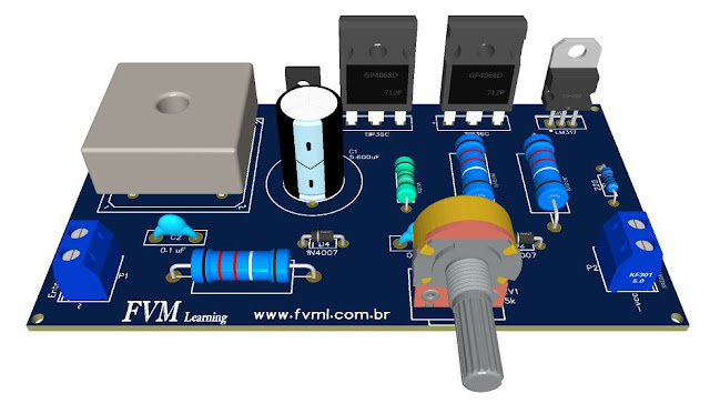
- Adjustable Power Supply 1.2V to 37V, 6A, Short Circuit Protection with LM317 and TIP36 + PCB
- Adjustable Switching Power Supply 5.1 to 40V, 2.5 Amp using L4960 + PCB
- Symmetrical Adjustable Power Supply 1.25V to 47V 10 Amps with Short Circuit Protection + PCB
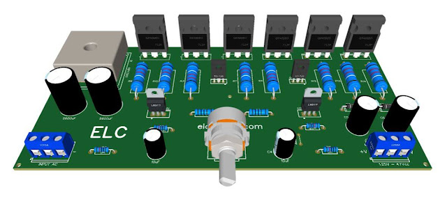
- Adjustable Power Supply 1.2 to 37V High Current 20A with LM317 and TIP35C + PCB
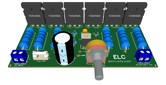
- Adjustable Power Supply 1.25v to 57V, 6 Amps with TIP36C + LM317HV + PCB
- Adjustable Power Supply 1.25v to 33V, 3 Amps with LM350 + PCB
- Stabilized Power Supply 13.8V High Current 10 Amps with PCB
In Figure 2 - you will find the description of the input, output and ground pins. There are also other types of encapsulation, as this TO - 3P is the most common.
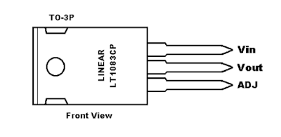 |
| Fig. 2 - Pinout LT1083 |
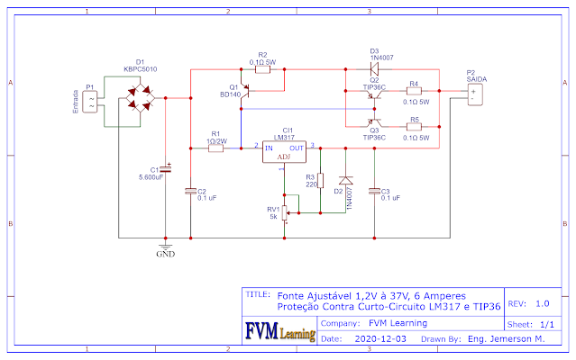
The schematic shown in Figure 3 is quite simple and similar to the schematics we have shown here on our website before, such as LM350, LM338, LM317 and others, always following the line of simplicity and ease of assembly.
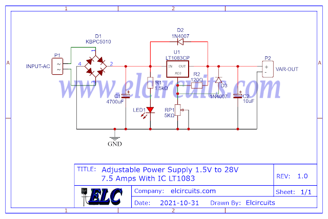 |
| Fig. 3 - Schematic diagram of adjustable power supply LT1083 |
All LT1083 series voltage regulators are pin-compatible with the more familiar three-terminal voltage regulators, as mentioned above. These devices require a 10 μF output capacitor, which is usually included in most regulator designs.
Unlike PNP regulators where up to 10% of the production current is wasted as quiescent current, the LT1083 flows quiescent current to the load, increasing efficiency.
Features
- 7.5A output current
- Three terminals pin-compatible
- Operates down to 1V loss
- Guaranteed cut-off voltage at various current levels
- Line regulation: 0.015%
- Load regulation: 0.1%
- 100% Thermal Limit Functional Test
Applications
- High Efficiency Linear Regulators
- Adjustable voltage regulators Constant current regulators
- Battery Chargers
- Desktop power supplies
Component List
- IC .......... LT1083Voltage Regulator Integrated Circuit
- D1 ......... KBPC1510 Bridge Rectifier diodes for 15 Amps or more as KBPC5010 for 50A
- C1 ......... 4.700uF - 50V Electrolytic capacitor
- C2 ......... 10uF - 50V Electrolytic capacitor
- R1 ......... 120 ohm -1/4W Resistor - (brown, red, brown, gold)
- R1 ......... 1.5K ohm -1/4W Resistor - (brown, green, red, gold)
- P1 ......... 5K ohms potentiometer
- P1, P2 ... Screw Terminal Type 5mm 2-Pin Connector
- Others ... Wires, solders, printed circuit board, etc.
Download
We provide the files with the PCB, the schematic, the PDF, GERBER and JPG, PNG and provide a direct link for free download and a direct link, "MEGA".
Click on the direct link to download the files: Layout PCB, PDF, GERBER, JPG
If you have any questions, suggestions or corrections, please leave them in the comments and we will answer them soon.
Subscribe to our blog!!! Click here - elcircuits.com!!!
My Best Regards!!!