Showing posts with label Transistor Amplifier. Show all posts

Monday, May 24, 2021

Simple 100W Power Amplifier using TIP142 NPN and TIP147 PNP transistors + PCB

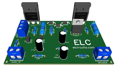
Fig 1 - PCB 100W Power Amplifier - TIP142 and TIP147 Transistors

This is a low complexity amplifier, which can be easily assembled by anyone who has basic knowledge in electronics.

This amplifier works with a Class B output stage with a complementary output pair formed by the TIP142 and TIP147 Darlington Transistors.

Operation

The input stage, is formed by a differential pair Q1 and Q2, which are two PNPs A733 transistors, the Q1 transistor receive the input signal for amplification, and Q2 receives the Feedback signal.

Thus assembling a signal loop making with the differential amplifier to control the signal giving stability to the amplifier and avoiding distortion in the circuit.

The second stage consists of a TIP41 transistor, which functions as a Drive, which receives the signal from the differential pair and amplifies it to delivery a sufficient current at the base of the output transistors.
This amplifier has an output power of approximately 100 watts, to get this output power will depend on the Power Supply voltage, with a supply voltage of + 50V / - 50V, with a current of 3A.

In our tests, it was possible to get a little more than 100W. The schematic diagram circuit, is in Figure 2 below, it is a very simple circuit to build, with few external components.

However, be careful, it works with a total voltage of 90V, be careful not to change any component polarity, don't short the amplifier circuit.
Fig 2 - Schematic Simple 100W Power Amplifier with  TIP142 NPN and TIP147 PNP transistors

Power supply

The power supply for this circuit amplifier is symmetrical, in our tests a Transformer with a +36V 0V -36V AC, center-tape was used, with a current 3 Amperes, after the CA voltage goes through the rectification, it will average 50V DC.

Components List

  • Semiconductor 
    • Q1, Q2 .... A733 - PNP transistor 
    • Q3 ........... TIP41C - NPN transistor
    • Q4 ........... TIP142 - NPN power transistor 
    • Q5 ............TIP147 - PNP power transistor 
    • D1, D2 .... 1N4007 - Diode 

  • Resistors 
    • R1, R2 ..... 22K ohms - 1/8W - Resistor  - (red, red, orange, gold)
    • R3 ........... 1K5 ohms - 1/8W - Resistor  - (brown, green, red, gold)
    • R4 ........... 220 ohms - 1/8W - Resistor  - (red, red, brown, gold)
    • R5 ........... 27K ohms - 1/8W - Resistor  - (red, violet, orange, gold)
    • R6 ........... 27 ohms - 1/8W - Resistor  - (red, violet, black, gold)
    • R7, R8 .... 3K3 ohms - 1W - Resistor  - (orange, orange, red, gold)
    • R9, R10 ... 022 ohms - 3W - Resistor  - (red, red, gold, silver)

  • Capacitors
    • C1 .......... 2.2uF - 25V - Electrolytic capacitor 
    • C2 .......... 100uF - 63V - Electrolytic capacitor 
    • C3 .......... 10uF - 63V - Electrolytic capacitor

  • Miscellaneous 
    • P1, P2 ..... Block 5mm 2 Pin weldable terminal Connector
    • P3 ........... Block 5mm 3 Pin weldable terminal Connector
    • Others .... Printed Circuit Board, Wires, Solders, Etc.

We are offering the PCI - Printed Circuit Board, in GERBER, PDF and PNG files, for you who want to do the most optimized assembly, either at home.

If you prefer in a company that develops the board, you can is downloading and make the files in the Download option below.

Files to download, Direct Link:

Click on the link beside: GERBER, PDF and PNG files

If you have any questions, suggestions or corrections, please leave them in the comments and we will answer them soon.

Subscribe to our blog!!! Click here - elcircuits.com!!!

My Best Regards!!!

Friday, May 21, 2021

200W RMS Power Amplifier using 2SC2500 AND 2SA1943 transistors + PCB

Fig. 1 - 200W RMS Power Amplifier using 2SC2500 AND 2SA1943 transistors


This Power Amplifier have a moderate sound quality, and it's a simple circuit to assemble, using 4 complementary output transistors, 2 x NPN 2SC2500 and 2 x PNP 2SA1943

This amplifier is quite common to find and it has a good sound quality, uses specific power transistors for audio, making these amplifiers a good circuit amplifier to building.


This is a power amplifier, posted by our partner fvml.com.br, we are authorized to replicate any post, so we took these posts from them and implemented the volume control and changed the layout a little. This partnership allows us to do this, and they are also free to repost our posts.

The circuit is supplied with a symmetrical power supply and can be supplied with a voltage between 30V to 65V, for greater performance you must use the 60V, with at least current 4 Amperes.

The schematic diagram is shown in Figure 2 below, it is a simple amplifier, and often found on the internet for sale, it has a good quality and complies with the promised power.
Fig. 2 - 200W RMS Power Amplifier with 2SC2500 and 2SA1943

Power supply

The power supply for this circuit amplifier is symmetrical, in our tests a Transformer with a 42V - 0 - 42V center-tape was used, with a 5 Amperes current, you can use a lower current, up to 4 Amps minimum, which will play perfectly.

Nothing prevents you from using a lower voltage, as this amplifier has a tolerance regarding its supply voltage, and can normally play "with loss in output power" with voltages ranging from 24V to 60V without too many problems.

Components List

  • Q1, Q2, Q3 .................. A1015 - PNP transistor 
  • Q5, Q6 ......................... TIP41C - NPN transistor
  • Q4, Q7 ......................... TIP42C- PNP transistor
  • Q8, Q10 ....................... 2SC5200 - NPN power transistor 
  • Q9, Q11 ....................... 2SA1943 - PNP power transistor 
  • D1, D2, D3, D4, D5 .... 1N4007 - Diode 
  • P1 ................................ 47K - Potentiometer 
  • C1 ............................... 2.2uF - 25V - Electrolytic capacitor 
  • C2 ............................... 47uF - 63V - Electrolytic capacitor 
  • C3 ............................... 330pF - Ceramic / polyester capacitor 
  • C4 ............................... 100nF ceramic / polyester capacitor
  • R1 ............................... 10K ohms - 1 / 4W - Resistor  - (brown, black, orange)
  • R2 ............................... 18k ohms - 1 / 4W - Resistor  - (brown, gray, orange)
  • R3 ............................... 820 ohms - 1 / 4W - Resistor  - (gray, red, brown)
  • R4 ............................... 270 ohms - 1W - Resistor  - (red, violet, brown)
  • R5 ............................... 1K ohms - 1 / 4W - Resistor  - (brown, black, red)
  • R6 ............................... 18K ohms - 1 / 4W - Resistor  - (brown, gray, orange)
  • R7 ............................... 330 ohms - 1 / 4W - Resistor  - (orange, orange, brown)
  • R8 ............................... 56 ohms - 1W - Resistor  - (green, blue, black)
  • R9 ............................... 27 ohms - 1W - Resistor  - (red, violet, black)
  • R10, R11 .................... 6R8 ohms - 1W - Resistor - (blue, gray, gold)
  • R12, R13 .................... 100 ohms - 1W - Resistor  - (brown, black, brown)
  • R14, R15, R16, R17 ... 033 ohms - 5W - Resistor  - (orange, orange, gold)
  • R18, R19 .................... 10 ohm resistor - 1W - (brown, black, black)
  • B1, B2 ........................ WJ2EDGVC-5.08-2P Connector
  • B3 ............................... WJ2EDGVC-5.08-3P connector
  • L1 ............................... Coil - 5uH Air Core
  • Others ......................... Printed Circuit Board, Wires, Solders and Etc.

We are offering the PCB - Printed Circuit Board, in GERBER, PDF and PNG files, for you who want to do the most optimized assembly, either at home.

If you prefer in a company that develops the board, you can is downloading and make the files in the Download option below.

Files to download, Direct Link:

Click on the link beside: GERBER, PDF and PNG files

If you have any questions, suggestions or corrections, please leave them in the comments and we will answer them soon.

Subscribe to our blog!!! Click here - elcircuits.com!!!

My Best Regards!!!

Sunday, April 18, 2021

300W RMS Power Amplifier - 2SC3858 and 2SA1494 Transistors + PCB

Fig. 1 - PCB 300W RMS Power Amplifier - 2SC3858 and 2SA1494 Transistors


This is a 300W RMS Power Amplifier using complementary power transistors 2SC3858 and 2SA1494, this circuit amplifier isn't so simple to building, it will be necessary to have at least a little experience in electronics.

To set up this circuit, its complexity is moderate, but, if you haven't skills in electronics circuits, we advise you not to do it, however, if you really want to do it, call someone with experience, to help you.

This amplifier has an excellent audio quality, and use four output power transistors, it reaches a sound power of 300W RMS under load of 4 ohms, powered with a symmetric power supply. You can check the schematic diagram in Figure 2 below.

Fig. 2 - Schematic 300W RMS Power Amplifier - 2SC3858 and 2SA1494 Transistors

Power Supply

The power supply consists of a symmetrical transformer 45V - 0 - 45V center tape, 6 Amperes current supply, can be used. After rectified, we will have approximately 63Vcc at the output of the symmetrical power supply .

Components list

  • Q1, Q2, Q3, Q5 ......... C1815 NPN Transistor
  • Q4 .............................. A1015 PNP Transistor 
  • Q7 .............................. TIP 42C PNP Transistor
  • Q8, Q9 ....................... 2SC3858 NPN Power Transistor
  • Q10, Q11 ................... 2SA1494 PNP Power Transistor
  • Q6 .............................. TIP41C NPN Transistor

  • D1 to D7 .................... 1N4148 diode, or equivalent diode 1N4001 
  • C1, C4 ......................... 2.2uF - 25V Electrolytic Capacitor   
  • C2 ............................... 220pF Polyester / Ceramic Capacitor 
  • C8 ............................... 100nF Polyester / Ceramic Capacitor 

  • R2, R10 ....................... 47k ohms resistor (yellow, violet, orange, gold)
  • R3, R5 ......................... 2.2k ohms resistor (red, red, red, gold)
  • R4 ................................ 270 ohms resistor (red, violet, black, gold)
  • R6, R7 ......................... 51K ohms - 1/2W resistor (green, brown, orange, gold)
  • R8, R9, ........................ 100 ohms resistor (brown, brown, black, gold)
  • R11 .............................. 470 ohms resistor (yellow, violet, brown, gold)
  • R12 .............................. 390 ohms resistor (orange, white, brown, gold)
  • R13, R14 ..................... 100 ohms - 2W resistor (brown, brown, black, gold)
  • R17, R18 ...................... 6R8 ohms - 1W resistor (blue, gray, gold, gold)
  • R15, R16, R19, R20 .... 100 ohms - 1W resistor (brown, brown, black, gold)
  • R21, R22, R23, R24 .... 0.33 ohms - 5W resistor (orange, orange, gold, gold)
  • R25 .............................. 22 ohms resistor (red, red, black gold)
  • R26 .............................. 10 ohms - 1W resistor - (brown, black, black. gold)

  • P1, P2 ....... 2 Pin - PCB Terminal Blocks - EK500V-XXP 20A - or equivalent
  • P3 ............. 3 Pin - PCB Terminal Blocks - EK500V-XXP 20A - or equivalent

  • L1 ............. 5uH - Air Core Coil 10 Turns 18AWG, 3/8" Core

  • Others ...... Loudspeaker, Wires, Solders and Etc.


For those who want to download materials such as the schematic diagram in PDF, PCB Layout,  GERBER and JPG, we are providing a direct link to download all the material.

Direct link to download

Click in the link below to download the Files: PCB Layout, PDF, GERBER, JPG

If you have any questions, suggestions or corrections, please leave them in the comments and we will answer them soon.

Subscribe to our blog!!! Click here - elcircuits.com!!!

My Best Regards!!!

Thursday, April 1, 2021

50W RMS Audio Amplifier with IRF530 and IRF9530 Mosfet + PCB

Fig. 1 - PCB 50W Audio Amplifier

For Portuguese version, click here!

This circuit amplifier is very simple to building, however, although simple, it has an excellent audio quality, and with just two output transistors, it reaches a sound power of 50W RMS under load of 8 ohms, which is enough for a great home sound system, or for speakers for musical instruments ... the possibilities are endless.

The first stage of the amplifier is a differential amplifier based on the transistors Q1 and Q2. Capacitor C2 is the input DC decouple, R1 limits the input current and capacitor C1 deflects unwanted high frequencies.

You might also be interested in:

The second stage is the drive stage composed of the transistor Q3 BC546, which supplies the output power stage, and the transistor Q4 is the bias regulating transistor, which, through the PR1 trimpot, adjusts the quiescent current in the transistors.

The output stage is a complementary push-pull stage based on the IRF530 and IRF9530 MOSFETs. The output is coupled to the speaker using the L1 inductor

The network composed in series by hairs, resistor R14 and capacitor C5, is intended to reduce output noise. And Capacitors C6 and C7 are power supply voltage filters. 

For coil L1: Wrap 12 turns of enameled copper wire in a 1cm diameter without core.

A Heatsink is required for MOSFETs. That should have the average dimensions of 8x4x4 inches will already work without problems.

You can check the schematic diagram in Figure 2 below.

Fig. 2 - 50 Watt Amplifier Circuit Diagram

Power Supply

The power supply consists of a symmetrical transformer 35Vcc - 0 - 35V center tape, with a current of 3 Amperes, a lower current, up to 2 Amperes minimum, can be used, which will play without any problems. 

Nothing prevents you from using a higher or lower voltage, as this amplifier has a tolerance for the supply voltage, and can normally play "with small attenuations in the output power" with voltages ranging from 27V to 40V without too many problems.

It also has great stability and we can use, if you have, a SMPS power supply, and this is clear with Center-Tape, that is to say a power supply with central socket.

Component List

  • Q1, Q2 ................ 2N3906 Transistor (or BC558, A733)
  • Q3, Q4 ................ 2N3904 Transistor (or BC548)
  • Q5 ....................... IRF9530P Mosfet P Transistor
  • Q6 ....................... IRF530P Mosfet N Transistor

  • D1 ....................... 1N4007 Diode 

  • C1 ....................... 220pF ceramic / polyester capacitor  
  • C2, C3, C4 .......... 47uF - 35V electrolytic capacitor 
  • C5 ....................... 68nF ceramic / polyester capacitor 
  • C6, C7 ................ 470uF - 50V electrolytic capacitor 

  • R1, R8 ................ 4.7k ohms resistor (yellow, violet, red, gold)
  • R2, R7 ................ 47k ohms resistor (yellow, violet, orange, gold)
  • R3 ....................... 560 ohms resistor (green, blue, brown, gold)
  • R4 ....................... 15k ohms resistor (brown, green, orange, gold)
  • R5 ....................... 1.2k ohms resistor (brown, red, red, gold)
  • R6 ....................... 2.2k ohms resistor (red, red, red, gold)
  • R9 ....................... 10k ohms resistor (brown, black, orange, gold)
  • R10 ..................... 820 ohms resistor (gray, red, brown, gold)
  • R11, R12 ............ 2.7k ohms resistor (red, violet, red, gold)
  • R13, R14 ............ 680 ohms resistor (blue, gray, brown, gold)
  • R15 ..................... 10 ohm - 3W resistor - (brown, black, black. gold)

  • L1 ........................ 5uH - Air Core Coil 10 Turns 18AWG, 3/8" Core

  • RP1 ..................... 1K ohms variable resistor - Trimpot 

  • Others ................. Loudspeaker, Wires, Solders and Etc.

For those who want to download materials such as the schematic diagram in PDF, PCB Layout,  GERBER and JPG, we are providing a direct link to download all the material.

Direct link to download

Click in the link below to download the Files: PCB Layout, PDF, GERBER, JPG

If you have any questions, suggestions or corrections, please leave them in the comments and we will answer them soon.

Subscribe to our blog!!! Click here - elcircuits.com!!!

My Best Regards!!!

Saturday, March 20, 2021

100W RMS Power Amplifier using 2 NPN 2SC5200 Output Transistors + PCB

Fig. 1 - 100W RMS Power Amplifier using 2 NPN 2SC5200 Output Transistors + PCB

For Portuguese version, click here!

We usually have amplifiers with complementary outputs on most amplifier designs, and in a vast majority of amplifiers, it's quite normal to use the complementary NPN 2SC5200 transistors in conjunction with the PNP 2SA1943.

This type of amplifier is very common and good quality, because these transistors are specific for high fidelity amplification.

You might also be interested in:

We'll build an amplifier circuit that uses the same concepts as two output transistors, but we will use two NPN 2SA5200 output transistors. Which is very interesting for those who like to test other types of transistors to evaluate the quality, distortions, powers. Etc.

The schematic diagram is in Figure 2 below, it is a simple amplifier, it has a satisfactory quality.

Fig. 2 - 100W RMS Power Amplifier with 2 NSC 2SC5200 Transistors at Output

Power Supply

The power supply consists of a symmetrical transformer 32V - 0 - 32V center tape, with a current of 5 Amperes, a lower current, up to 3 Amperes minimum, can be used, which will play without any problems.

Nothing prevents you from using a higher or lower voltage, as this amplifier has a tolerance for the supply voltage, and can normally play “with small attenuation in the output power” with voltages ranging from 18V to 55V without too many difficulties.

It also has great stability, and we can use, if you have, a SMPS power supply, and this is clear with Center-Tape, that is to say a power supply with central socket.

Component List

  • Q1, Q2 ............... Transistor A733
  • Q3, Q4 ............... TIP41C transistor
  • Q5 ...................... TIP42C transistor
  • Q6, Q7 ............... 2SC5200 Power Transistor

  • D1, D2, D3 ........ Diode 1N4007

  • C1 ....................... 0.47uF Polyester capacitor 
  • C2, C4, C5 .......... 47uF - 63V electrolytic capacitor 
  • C3 ....................... 100nF ceramic / polyester capacitor 
  • C6 ....................... 150pF ceramic / polyester capacitor 
  • C7, C8 ................ 1nF ceramic / polyester capacitor

  • R1 ....................... 22k ohms resistor (red, red, orange, gold)
  • R2 ....................... 15k ohms resistor (brown, green, orange, gold)
  • R3, R7 ................. 680 ohms resistor (blue, gray, brown, gold)
  • R4 ....................... 33 ohms resistor (orange, orange, black, gold)
  • R5 ....................... 560 ohms - 1W resistor (green, blue, brown, gold)
  • R6 ....................... 56k ohms resistor (green, blue, orange, gold)
  • R8, R9 ................ 4.7k ohms resistor (yellow, violet, red, gold)
  • R10 ..................... 10 ohm resistor - (brown, black, black. gold)
  • R11 ..................... 120 ohms - 1W resistor (brown, red, brown, gold)
  • R12, R13 ............ 100 ohms - 1W resistor (brown, black, brown, gold)
  • R14, R15 ............ 0.47 ohms - 5W resistor (yellow, violet, silver, gold)

  • Others ................. PCB, Heat Sink, Loudspeaker, Wires, Solders, Etc.

For those who want to download materials such as the schematic diagram in PDF, PCB Layout,  GERBER and JPG, we are providing a direct link to download all the material.

Direct link to download

Click in the link below to download the Files: PCB Layout, PDF, GERBER, JPG

If you have any questions, suggestions or corrections, please leave them in the comments and we will answer them soon.

Subscribe to our blog!!! Click here - elcircuits.com!!!

My Best Regards!!!