 Português
 Español
50W RMS Audio Amplifier using IRF530 and IRF9530 MOSFETs + PCB
50W RMS Audio Amplifier using IRF530 and IRF9530 Mosfet
This circuit amplifier is very simple to building, however, although simple, it has an excellent audio quality, and with just two output transistors, it reaches a sound power of 50W RMS under load of 8 ohms, which is enough for a great home sound system, or for speakers for musical instruments … the possibilities are endless.
The first stage of the amplifier is a differential amplifier based on the transistors Q1 and Q2. Capacitor C2 is the input DC decouple, R1 limits the input current and capacitor C1 deflects unwanted high frequencies.
The second stage is the drive stage composed of the transistor Q3 BC546, which supplies the output power stage, and the transistor Q4 is the bias regulating transistor, which, through the PR1 trimpot, adjusts the quiescent current in the transistors.
The output stage is a complementary push-pull stage based on the IRF530 and IRF9530 MOSFETs. The output is coupled to the speaker using the L1 inductor.
The network composed in series by hairs, resistor R14 and capacitor C5, is intended to reduce output noise. And Capacitors C6 and C7 are power supply voltage filters.
For coil L1: Wrap 12 turns of enameled copper wire in a 1cm diameter without core.
A Heatsink is required for MOSFETs. That should have the average dimensions of 8x4x4 inches will already work without problems.
Circuit Schematic Diagram
You can check the schematic diagram in Figure 2 below.
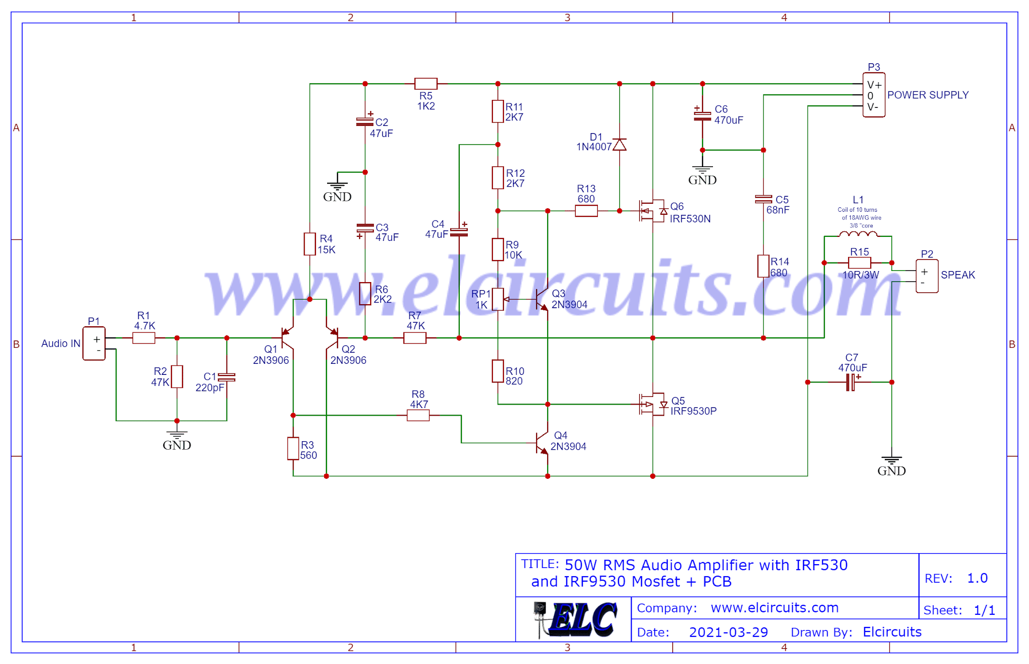
Fig. 2 – 50 Watt Amplifier Circuit Diagram
You might also be interested in:
- 400W Class AB Amplifier using MJL4281A and MJL4302A transistors + PCB
- Simple 100W Power Amplifier with TIP142 NPN and TIP147 PNP transistors + PCB
- 200W RMS Power Amplifier With 2SC2500 AND 2SA1943 + PCB
- 300W RMS Power Amplifier – 2SC3858 and 2SA1494 Transistors + PCB
- 100W RMS Power Amplifier With 2 NPN 2SC5200 Transistors At Output + PCB
- Simple 3 Transistors Power Amplifier push a 600W RMS Subwoofer + PCB
Power Supply
The power supply consists of a symmetrical transformer 35Vcc – 0 – 35V center tape, with a current of 3 Amperes, a lower current, up to 2 Amperes minimum, can be used, which will play without any problems.
Nothing prevents you from using a higher or lower voltage, as this amplifier has a tolerance for the supply voltage, and can normally play “with small attenuations in the output power” with voltages ranging from 27V to 40V without too many problems.
It also has great stability and we can use, if you have, a SMPS power supply, and this is clear with Center-Tape, that is to say a power supply with central socket.
Component List
- Q1, Q2 ……………. 2N3906 Transistor (or BC558, A733)
- Q3, Q4 ……………. 2N3904 Transistor (or BC548)
- Q5 ………………….. IRF9530P Mosfet P Transistor
- Q6 ………………….. IRF530P Mosfet N Transistor
- D1 ………………….. 1N4007 Diode
- C1 ………………….. 220pF ceramic / polyester capacitor
- C2, C3, C4 ………. 47uF – 35V electrolytic capacitor
- C5 ………………….. 68nF ceramic / polyester capacitor
- C6, C7 ……………. 470uF – 50V electrolytic capacitor
- R1, R8 ……………. 4.7k ohms resistor (yellow, violet, red, gold)
- R2, R7 ……………. 47k ohms resistor (yellow, violet, orange, gold)
- R3 ………………….. 560 ohms resistor (green, blue, brown, gold)
- R4 ………………….. 15k ohms resistor (brown, green, orange, gold)
- R5 ………………….. 1.2k ohms resistor (brown, red, red, gold)
- R6 ………………….. 2.2k ohms resistor (red, red, red, gold)
- R9 ………………….. 10k ohms resistor (brown, black, orange, gold)
- R10 ………………… 820 ohms resistor (gray, red, brown, gold)
- R11, R12 ………… 2.7k ohms resistor (red, violet, red, gold)
- R13, R14 ………… 680 ohms resistor (blue, gray, brown, gold)
- R15 ………………… 10 ohm – 3W resistor – (brown, black, black. gold)
- L1 …………………… 5uH – Air Core Coil 10 Turns 18AWG, 3/8″ Core
- RP1 ………………… 1K ohms variable resistor – Trimpot
- Others …………….. Loudspeaker, Wires, Solders and Etc.
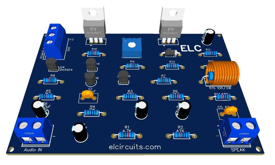
🖨️ Printed Circuit Board – Download
We are offering the PCB – Printed Circuit Board, in GERBER, PDF and PNG files, for you who want to do the most optimized assembly, either at home.
If you prefer in a company that develops the board, you can is downloading and make the files in the Download option below.
📥 Files to Download, Direct Link:
Click on the link beside: PCB Layout, PDF, GERBER, JPG
✨ Our Gratitude and Next Steps
We sincerely hope this guide has been useful and enriching for your projects! Thank you for dedicating your time to this content.
Your Feedback is Invaluable:
Have any questions, suggestions, or corrections? Feel free to share them in the comments below! Your contribution helps us refine this content for the entire ElCircuits community.
If you found this guide helpful, spread the knowledge!
🔗 Share This Guide
Best regards,
The ElCircuits Team ⚡


