400W Class AB Power Amplifier using MJL4281A / MJL4302A + PCB
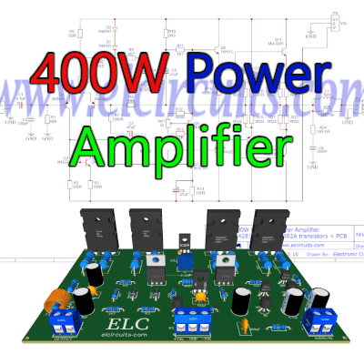
400W Class AB Amplifier using MJL4281A and MJL4302A transistors + PCB
The amplifier circuit is 400W RMS per channel, if you want to make two of these boards, they will be 800W RMS, that is, high power with great sound quality and stability.
It uses 4 power transistors on the output; two NPN transistors MJL4281 and two PNP MJL4302, forming a double pair of complementary transistors.
This amplifier circuit can be used for virtually any type of application that requires an amplifier of high performance, low noise and low distortion, and excellent sound quality.
🏋️♀️ The Power Transistors
The MJL4281A and MJL4302A transistors are power transistors designed for high power audio, they have a collector-emitter sustaining voltage of 350 V, high gain – 80 to 240, with hFE = 50 (min) 8A collector current. And a low harmonic distortion, which makes a transistor exceptional for high power operation and audio quality.
🔌 The Circuit
The complexity of the circuit is at an advanced level, it is not recommended for those who do not have experience in electronics and in assembling amplifier circuits, you must have minimal knowledge at an advanced level to assemble this type of power amplifier.
The schematic diagram of the complete circuit, shown in Figure 2 below, is a very robust amplifier, with great sound quality, and very stable, responding very well at all audible frequencies, with little attenuation in the auditory frequency range 20Hz to 20Khz.
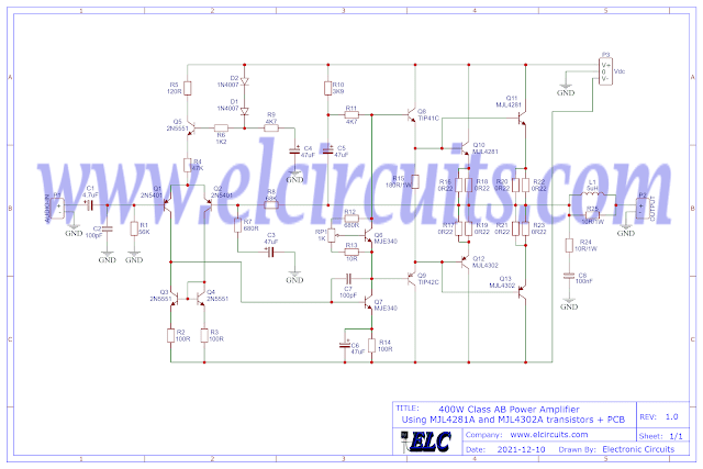
Fig. 2 – Schematic 400W Class AB Amplifier using MJL4281A and MJL4302A transistors
You might also be interested in:
- Build a 50W RMS Audio Amplifier with Mosfet | Complete DIY Guide
- 160W High Fidelity Amplifier using Mosfet 2SK1058 and 2SJ162 with PCB
- 440W Class AB Power Amplifier using Mosfet IRFP9240 and IRFP240 with PCB
- 200W RMS Power Amplifier With 2SC2500 AND 2SA1943 + PCB
- 300W RMS Power Amplifier – 2SC3858 and 2SA1494 Transistors + PCB
- 50W RMS Audio Amplifier with IRF530 and IRF9530 Mosfet + PCB
- 100W RMS Power Amplifier With 2 NPN 2SC5200 Transistors At Output + PCB
- Simple 3 Transistors Power Amplifier push a 600W RMS Subwoofer + PCB
⚡Power supply
The power supply is symmetrical, with a voltage of +65V | 0V | -65V, and direct current, with at least 6 Amps of current. For continuous use, we recommend 8A, especially if used in a subwoofer.
In Figure 3 below, we have a suggestion for a power supply that we use in our projects. In this article, besides having the schematic diagram with Printed Circuit Board, you will understand how to easily calculate your own Power Supply, with the desired voltage.
You can in the link below:
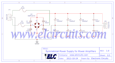
Fig. 3 – Symmetrical Power Supply for Power Amplifiers
🧾 Components List
- Q1, Q2 ………… 2N5401 PNP Transistor
- Q3, Q4, Q5 ….. 2N5551 NPN Transistor
- Q6, Q7 ………… MJE340 NPN Transistor
- Q8 ………………. TIP41 NPN Transistor
- Q9 ………………. TIP42 PNP Transistor
- Q10, Q11 ……… MJL4281 NPN Transistor
- Q12, Q13 ……… MJL4302 NPN Transistor
- D1, D2 …………. 1N4007 Diode
- R1 ……………….. 56KΩ resistor (green, blue, orange, gold)
- R2, R3, R14 ….. 100Ω resistor (brown, black, brown, gold)
- R4 ……………….. 47KΩ resistor (yellow, purple, orange, gold)
- R5 ……………….. 120Ω resistor (brown, red, brown, gold)
- R6 ……………….. 1K2Ω resistor (brown, red, red, gold)
- R7, R12 ………… 680Ω resistor (blue, gray, brown, gold)
- R8 ………………… 68KΩ resistor (blue, gray, orange, gold)
- R9, R11 ………… 4K7Ω resistor (yellow, red, purple, gold)
- R10 ……………… 3K9Ω resistor (orange, white, red, gold)
- R13 ……………… 10Ω resistor (brown, black, black, gold)
- R15 ……………… 180Ω / 1W resistor (brown, gray, brown, gold)
- R16 to R23 ……. 0.22Ω /5W resistor (red, red, gold, silver)
- R24, R25 ………. 10Ω / 1W resistor (brown, black, black, gold)
- RP1 ……………… 1K Potentiometer
- C1 …………………… 4.7uF / 25V electrolytic capacitor
- C2, C7 …………….. 100pF ceramic, polyester capacitor
- C3, C4, C5, C6 …. 47uF / 50V electrolytic capacitor
- C8 …………………… 100nF ceramic, polyester capacitor
- L1 ……………. 5uH – Air Core Coil 10 Turns 18AWG, 3/8″ Core
- P1, P2 ……….. Screw Terminal Type 5mm 2-Pin Connector
- P3 …………….. Screw Terminal Type 5mm 3-Pin Connector
- Others ………… PCB, tin, wires, heat sink, soldering Iron, etc.
🖨️ Printed Circuit Board (PCB)
We are offering the PCB – Printed Circuit Board, in GERBER, PDF and PNG files, for you who want to do the most optimized assembly, either at home.
If you prefer in a company that develops the board, you can download the files in the Download option below.

Fig. 4 – PCB – 400W Class AB Amplifier using MJL4281A and MJL4302A transistors
📥 Files to download, Direct Link:
Click on the link beside: GERBER, PDF and PNG files
✨ Our Gratitude and Next Steps
We sincerely hope this guide has been useful and enriching for your projects! Thank you for dedicating your time to this content.
Your Feedback is Invaluable:
Have any questions, suggestions, or corrections? Feel free to share them in the comments below! Your contribution helps us refine this content for the entire ElCircuits community.
If you found this guide helpful, spread the knowledge!
🔗 Share This Guide
Best regards,
The ElCircuits Team ⚡

 Português
 Español