 Português
 Español
160W Hi-Fi Mosfet Amplifier with 2SK1058 / 2SJ162 Transistors + PCB

Fig. 1 – 160W High Fidelity Amplifier using Mosfet 2SK1058 and 2SJ162 with PCB
This is a High Fidelity power amplifier, which uses 2 pairs of complementary MOSFETs output transistors, 2SK1058 and 2SJ162, which gives us a 160W power output.
The circuit is simple to assemble, assuming you have advanced knowledge in electronics, you will be able to assemble this circuit without too much difficulty.
Basic operation of circuit
This amplifier has a few many steps, and we could break down each component, but it would certainly be too long, so let’s explain the main stage of amplifier process.
🔌 Amplifier Circuit Diagram
The 160W High Fidelity Amplifier circuit diagram is shown in Figure 2 below. It uses 4 output Mosfet power transistors, 2 transistors for the positive cycle and 2 transistors for the negative cycle.

Fig. 2 – Schematic Circuits 160W High Fidelity Amplifier using Mosfet 2SK1058 and 2SJ162
1️⃣ We will start with first Stage:
It is formed by a pair of MPSA56 PNP transistors, they form the input of the differential amplifier. The main characteristic is to amplify the difference of the input signals without amplifying the common mode signal.
2️⃣ In the second stage:
We have two pairs of transistors, 2 NPN BD139 transistors and 2 PNP TIP140 transistors, they constitute a differential current source pair formed by BD139 transistors pair. And with a current mirror formed by BD140 transistors pair, in Cascade mode creating a telescopic amplifier stage.
3️⃣ In the third stage:
It is formed by 4 Output MOSFETs transistors, two N-channel type transistors 2SK1058 and other two P-channel type transistors 2SJ162. They receive the signal from stage 2 which is a module in Cascade, as already explained, and deliver to the output load, formed by the speaker.
The output transistors should be equipped with a Heat Sink, and should be electrically separated with thermal insulators.
You might also be interested in:
- Build a 50W RMS Audio Amplifier with Mosfet | Complete DIY Guide
- 440W Class AB Power Amplifier using Mosfet IRFP9240 and IRFP240 with PCB
- 400W Class AB Amplifier using MJL4281A and MJL4302A transistors + PCB
- Simple 100W Power Amplifier with TIP142 NPN and TIP147 PNP transistors + PCB
- 200W RMS Power Amplifier With 2SC2500 AND 2SA1943 + PCB
- 300W RMS Power Amplifier – 2SC3858 and 2SA1494 Transistors + PCB
- 50W RMS Audio Amplifier with IRF530 and IRF9530 Mosfet + PCB
- 100W RMS Power Amplifier With 2 NPN 2SC5200 Transistors At Output + PCB
⚡ Power Supply
The power supply is a symmetrical source, +Vdc GND -Vdc, and must contain a current capable of supporting the total power of the Amplifier.
If the circuit is used in MONO mode “One channel“, the recommended current is 4 Amperes. If a STEREO version “Two channels” is used, the current should be doubled to 8 Amperes.
The amplifier work voltage is ±45Vdc SYMMETRICAL, to be used with an output load between 4 to 8 ohms.
🔌 Power Supply Circuit Diagram
In Figure 3 below, we have a suggestion for a power supply that we use in our projects. In this article, besides having the schematic diagram with the Printed Circuit Board, you will understand how to easily calculate your own Power Supply, with the desired voltage.
You can in the link below:
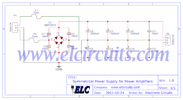
Fig. 3 – Symmetrical Power Supply for Power Amplifiers
Components List
Semiconductors
- Q1 …………………….. MPSA56 PNP Transistor
- Q3, Q4 ………………. BD139 NPN Transistor
- Q5, Q6 ………………. BD140 PNP Transistor
- Q7, Q8 ………………. 2SK1058 N-Channel Mosfet Transistor
- Q9, Q10 …………….. 2SJ162 P-Channel Mosfet Transistor
- D1, D2 ………………. 1N4007 Diode
Resistor
- R1, R2, R10 ……………. 47KΩ (yellow, violet, orange, gold)
- R3, R4 …………………… 3K3Ω (orange, orange, red, gold)
- R5 …………………………. 1K2Ω (brown, red, red, gold)
- R6 …………………………. 10KΩ (brown, black, orange, gold)
- R7, R8 …………………… 1KΩ (brown, black, red, gold)
- R9 …………………………. 2K2Ω (red, red, red, gold)
- R11, R12, R13, R14 … 47Ω (yellow, violet, black, gold)
- R15, R16, R17, R18 … 022Ω (red, red, silver, gold)
- R19 ……………………….. 10Ω (brown, black, black, gold)
Capacitor
- C1 …………………… 4.7uF / 65V Electrolytic Capacitor
- C2, C4, C5 ……….. 470pF Ceramic Capacitor
- C3 …………………… 47uF / 65V Electrolytic Capacitor
- C6 …………………… 100nF Ceramic Capacitor
Miscellaneous
- P1, P2 ………. 2-pin PCB soldering terminal blocks
- P3 ……………. 3-pin PCB soldering terminal blocks
- Others ……… PCB, heat sink, power supply, wires, etc.
🖨️ Printed Circuit Board (PCB)
We are offering PCB – Printed Circuit Board, in GERBER, PDF and PNG files, for you who want to do the most optimized assembly, either at home.
If you prefer in a company that develops the board, you can download the files in the Download option below.
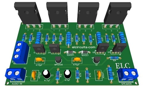
Fig. 3 – PCB 160W High Fidelity Amplifier using Mosfet 2SK1058 and 2SJ162
📥 Files to download, Direct Link:
✨ Our Gratitude and Next Steps
We sincerely hope this guide has been useful and enriching for your projects! Thank you for dedicating your time to this content.
Your Feedback is Invaluable:
Have any questions, suggestions, or corrections? Feel free to share them in the comments below! Your contribution helps us refine this content for the entire ElCircuits community.
If you found this guide helpful, spread the knowledge!
🔗 Share This Guide
Best regards,
The ElCircuits Team ⚡


