200W RMS Power Amplifier using 2SC5200 and 2SA1943 Transistors + PCB
200W RMS Power Amplifier using 2SC2500 AND 2SA1943 transistors
🔊 Build a Powerful 200W RMS Amplifier with Professional Quality!
Hello, electronics enthusiasts and high-quality audio lovers! Today we’re diving into a project that will elevate your audio experience to a new level: a 200W RMS power amplifier that combines assembly simplicity with exceptional performance.
This circuit uses 4 high-quality complementary output transistors: 2 NPN 2SC5200 transistors and 2 PNP 2SA1943 transistors. These components are specifically designed for audio applications, ensuring sound reproduction with high fidelity and low distortion.
💡 Expert Tip: This amplifier is quite popular in the DIY (Do It Yourself) audio community due to its excellent cost-benefit ratio and impressive sound performance. It’s an ideal choice for both beginners and more experienced enthusiasts!
Can’t find the exact transistors? No problem! We offer an exclusive tool on our website:
With this tool, you can find compatible alternatives that ensure the correct operation of your amplifier, even using components different from those originally recommended.
Power is supplied by a symmetrical power supply that can operate with voltages between 30V and 60V. To get maximum performance and take full advantage of the 200W RMS power, we recommend using 60V with a current capacity of at least 4 Amperes.
🔍 Understanding the Circuit: Schematic Diagram
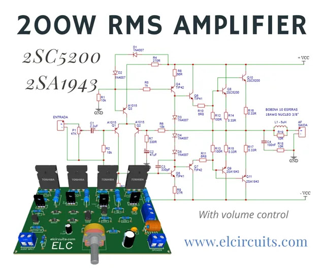
The schematic diagram, presented in Figure 2, reveals an elegant and efficient design. This amplifier uses a classic configuration that stands out for its simplicity and performance. It’s a circuit commonly found on the internet, but distinguished by its superior sound quality and ability to deliver the promised power.
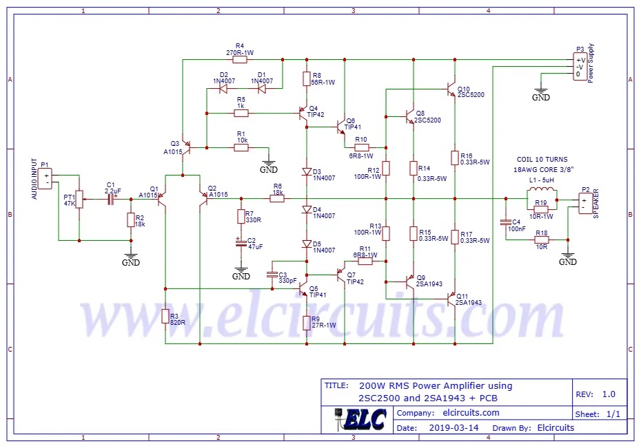
Fig. 2 – 200W RMS Power Amplifier with 2SC2500 and 2SA1943
🎓 Technical Analysis: This amplifier operates in class AB, offering an excellent balance between efficiency and sound quality. The configuration with complementary transistors (NPN and PNP) in the output ensures perfect symmetry in signal amplification, resulting in low harmonic distortion and excellent frequency response.
⚡ Power Supply: The Heart of Amplifier
The power supply is a crucial component for the performance of your amplifier. For this project, we use a symmetrical power supply with a center-tap transformer of 42V – 0 – 42V and current of 5 Amperes. This configuration provides stable and sufficient power to supply the circuit at its maximum power.
This amplifier demonstrates excellent flexibility regarding supply voltage. It can operate with voltages between 24V and 55V, although with a proportional reduction in output power. This feature makes the project versatile, allowing adaptations according to component availability in your region.
📊 Performance Table:
| Supply Voltage | Output Power (Approx.) | Minimum Recommended Current |
|---|---|---|
| 24V | 50W RMS | 2A |
| 36V | 100W RMS | 3A |
| 42V | 150W RMS | 3.5A |
| 55V-60V | 200W RMS | 4A-5A |
📋 Complete List of Materials
To facilitate your assembly, we’ve organized all necessary components into categories. Have this list on hand before starting your project!
Semiconductors
| Reference | Component | Specification |
|---|---|---|
| Q1, Q2, Q3 | PNP Transistor | A1015 |
| Q5, Q6 | NPN Transistor | TIP41C |
| Q4, Q7 | PNP Transistor | TIP42C |
| Q8, Q10 | NPN Power Transistor | 2SC5200 |
| Q9, Q11 | PNP Power Transistor | 2SA1943 |
| D1 à D5 | Diode | 1N4007 |
Capacitors
| Reference | Component | Specification |
|---|---|---|
| C1 | Electrolytic Capacitor | 2.2uF – 25V |
| C2 | Electrolytic Capacitor | 47uF – 63V |
| C3 | Ceramic/Polyester Capacitor | 330pF |
| C4 | Ceramic/Polyester Capacitor | 100nF |
Resistors
| Reference | Component | Specification |
|---|---|---|
| R1 | Resistor | 10K ohms – 1/4W (brown, black, orange, gold) |
| R2 | Resistor | 18k ohms – 1/4W (brown, gray, orange, gold) |
| R3 | Resistor | 820 ohms – 1/4W (gray, red, brown, gold) |
| R4 | Resistor | 270 ohms – 1W (red, violet, brown, gold) |
| R5 | Resistor | 1K ohms – 1/4W (brown, black, red, gold) |
| R6 | Resistor | 18K ohms – 1/4W (brown, gray, orange, gold) |
| R7 | Resistor | 330 ohms – 1/4W (orange, orange, brown, gold) |
| R8 | Resistor | 56 ohms – 1W (green, blue, black, gold) |
| R9 | Resistor | 27 ohms – 1W (red, violet, black, gold) |
| R10, R11 | Resistor | 6R8 ohms – 1W (blue, gray, gold, gold) |
| R12, R13 | Resistor | 100 ohms – 1W (brown, black, brown, gold) |
| R14 à R17 | Resistor | 033 ohms – 5W (orange, orange, gold) |
| R18, R19 | Resistor | 10 ohms – 1W (brown, black, black) |
| P1 | Potentiometer | 47K |
Miscellaneous
| Reference | Component | Specification |
|---|---|---|
| B1, B2 | Connector | WJ2EDGVC-5.08-2P |
| B3 | Connector | WJ2EDGVC-5.08-3P |
| L1 | Coil | 5uH Air Core |
| – | Others | Printed Circuit Board, Wires, Solder, etc. |
🖨️ Printed Circuit Board (PCB): Optimized Design
To facilitate your assembly, we’ve made the printed circuit board files available in various formats: PDF, GERBER and PNG. We also offer a direct link for free download of these files on a secure server, MEGA.
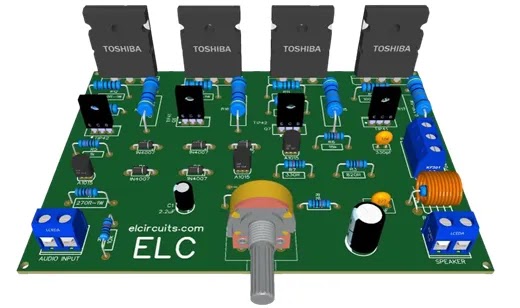
Fig. 3 – PCB – 200W RMS Power Amplifier with 2SC2500 and 2SA1943
🔧 Assembly Tips and Troubleshooting
To ensure the success of your project, we’ve separated some important tips:
- Component Organization: Before starting soldering, organize all components and verify you have everything necessary. This will save time and avoid frustrations.
- Polarity Check: Pay special attention to the polarity of electrolytic capacitors and diodes. An incorrect connection can permanently damage these components.
- Heat Sink: The power transistors (2SC5200 and 2SA1943) generate significant heat during operation. Make sure to install adequate heat sinks to ensure component longevity.
- Gradual Testing: After completing assembly, don’t immediately connect to speakers. First, check voltages at critical points in the circuit with a multimeter.
⚠️ Safety Warning: This amplifier operates with high voltages that can be dangerous. Always disconnect power before handling the circuit and, if possible, use a current-limited source during initial tests.
🎵 Applications and Performance
This 200W RMS amplifier is extremely versatile and can be used in various applications:
- Home Sound Systems: Ideal for those seeking high power and sound quality in residential audio systems.
- Recording Studios: The low distortion and flat frequency response make this amplifier an excellent choice for studio monitoring.
- Small Events and Presentations: With 200W RMS, this amplifier has enough power for small shows and live presentations.
- Home Theater Systems: Perfect for power channels in home theater systems, offering clarity and sound impact.
💡 Expert Tip: To get maximum performance from this amplifier, we recommend using speakers with impedance of 4 to 8 ohms and compatible power. Remember that the quality of speakers will directly influence the final sound experience!
🤔❓ Frequently Asked Questions (FAQ) – Your Questions Answered
1 Can I use different transistors than those specified?🔽
Yes, but with major caveats. The 2SC2500/2SA1943 transistors are specific for audio and were chosen for their linear characteristics. If you need to substitute, use our tool Equivalent BJT Transistor by Data Cross-Reference. Transistors like 2SC3858/2SA1494 or MJL3281A/MJL1302A may work, but require circuit adjustments.
2 What is the real power this amplifier delivers?🔽
With a ±35V supply and 4Ω load, this amplifier delivers 200W RMS real with THD below 0.1%. It’s important to note that many manufacturers “overpower” their amplifiers – this project is honest and delivers what it promises, without unrealistic specifications.
3 Do I need special heat sinks for the transistors?🔽
Yes! For continuous operation at 200W RMS, you need a heat sink with a minimum area of 500cm² per transistor (or 1000cm² total). For intermittent use (like at home), 300cm² per transistor is sufficient. Never operate without adequate heat sinks – transistors reach temperatures above 100°C.
4 Can I connect to 2Ω speakers?🔽
We don’t recommend it. Although technically possible, the current would double and the transistors would exceed their thermal limits. Use only 4Ω or 8Ω speakers. If you need more power at 2Ω, consider our 300W RMS amplifier project with MJL3281A/MJL1302A, specifically designed for low loads.
🔗 Related Projects That May Interest You
- 400W Class AB Amplifier using MJL4281A and MJL4302A transistors + PCB
- Simple 100W Power Amplifier with TIP142 NPN and TIP147 PNP transistors + PCB
- 300W RMS Power Amplifier – 2SC3858 and 2SA1494 Transistors + PCB
- 50W RMS Audio Amplifier with IRF530 and IRF9530 Mosfet + PCB
- 100W RMS Power Amplifier With 2 NPN 2SC5200 Transistors At Output + PCB
- Simple 3 Transistors Power Amplifier push a 600W RMS Subwoofer + PCB
🎓 Conclusion: An Amplifier That Unites Power and Quality
This 200W RMS amplifier with 2SC5200 and 2SA1943 transistors represents the perfect balance between assembly simplicity and high-quality sound performance. Whether for your home audio system, studio or small events, this project will deliver the power and clarity you’re looking for.
Remember that the final quality will depend not only on the components used, but also on care during assembly and quality of peripheral components, such as power supply and speakers.
🚀 Next Steps: After assembling your amplifier, consider building an appropriate speaker enclosure to maximize speaker performance. Soon, we’ll bring an article about speaker enclosure projects that perfectly match this amplifier!
💬 Join the Conversation!
We’d like to know your opinion! Have you built this amplifier? Do you have any questions or suggestions to improve the project? Leave your comment below and share your experience with our community of electronics enthusiasts!
✨ Our Gratitude and Next Steps
We sincerely hope this guide has been useful and enriching for your projects! Thank you for dedicating your time to this content.
Your Feedback is Invaluable:
Have any questions, suggestions, or corrections? Feel free to share them in the comments below! Your contribution helps us refine this content for the entire ElCircuits community.
If you found this guide helpful, spread the knowledge!
🔗 Share This Guide
Best regards,
The ElCircuits Team ⚡

 Português
 Español