Thursday, October 29, 2020

70W Stereo HI-FI Power Amplifier - High Fidelity using two TDA2050 IC's + PCB

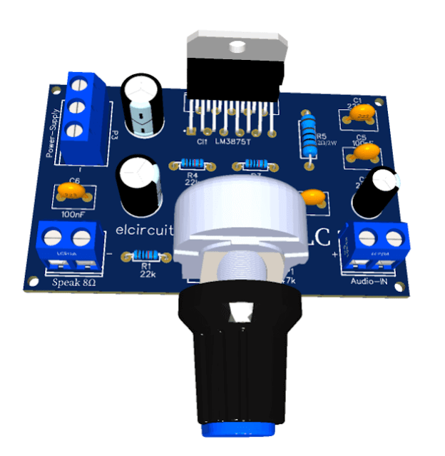
Fig. 1 - PCB 70W Power Amplifier TDA2050


In a previous post here on our website, we made an Amplifier Circuit with IC TDA2050 that delivers 35W RMS of power, it is an amplifier of excellent quality, and you can follow the link below:

HI-FI 32W Audio Amplifier – TDA2050 – Simple PS + PCB

In today's post we'll build a High Fidelity Stereo power Amplifier that provides 70W RMS - with two TDA2050 Integrated Circuits.

The TDA2050 Integrated Circuits

The TDA2050 is a monolithic integrated circuit in a Pentawatt® package, intended for use as a low frequency Class AB amplifier. Typically, it provides 35W RMS output power with 4 Ohm load, THD = 10%, VS = ± 18V, F = 1KHz, and up to 32W RMS with 8 Ohm load, THD = 10%, VS = ± 22V, F = 1KHz.

You might also be interested in:

The TDA2050 - provides the high current output and very low harmonic distortion, it incorporates a short circuit protection system, an arrangement to automatically limit the dissipated energy, in order to keep the working point of the output transistors within their safe area of ​​operation, that is, a conventional thermal shutdown system.

SHORT-CIRCUIT PROTECTION

The TDA2050 has an original circuit that limits the current of the internal output transistors, the maximum output current is a function of the voltage of the collector-emitter; hence the output transistors work within their safe operating area. 

This function can therefore be considered to be a peak power limitation, rather than a simple current limitation. It reduces the possibility of the device being damaged during an accidental short circuit at the output.

THERMAL SHUTDOWN

The presence of a thermal limiting circuit offers the following advantages:

  • An overload at the outlet (even if it is permanent), or an ambient temperature above the limit can be easily supported, as the Tj cannot exceed 150 ° C.
  • The heat sink may have a lower safety factor compared to that of a conventional circuit. There is no possibility of damage to the device due to the high junction temperature. If for some reason, the junction temperature increases up to 150 ° C, the thermal shutdown simply reduces the power dissipation in the current consumption.
  • The maximum allowed energy dissipation depends on the size of the external heat sink (i.e. thermal resistance); this power is dissipated depending on the ambient temperature for different thermal resistance.

The proposed circuit is a stereo power amplifier, it has two input channels and two output channels, and its schematic diagram is shown in Figure 2 below, and as we can see, it is the same circuit as the 35W amplifier, but it is duplicated making it stereo. 

The circuit is quite simple and can be easily assembled even by people who do not have so much experience in assembling electronic circuits, however, it is necessary to have knowledge of electronics.

Fig. 2 - Schematic Amplifier TDA2050

Component List

  • U1, U2 .................................................. TDA2050 Integrated Circuits
  • R1, R2, R3, R5, R8, R10, R11, R12 .... 1/4w 22KΩ Resistor
  • R4, R9 .................................................. 1/4w 680Ω Resistor
  • R6, R7 .................................................. 1/4w 2.2Ω Resistor
  • C1, C14 ................................................ 25V 2.2µF Electrolytic
  • C2, C15 ................................................ 25V  100µF Electrolytic
  • C3, C7, C8, C9 .................................... 35V  1o00µF Electrolytic
  • C4, C12 ............................................... 25V 22uF Electrolytic
  • C5, C11 ................................................ 100nF polyester
  • C6, C10 ................................................ 0.47µF polyester
  • RP1, RP2 ............................................. 47KΩ Potentiometer
  • P1, P3 …......….........................…........ Screw Terminal Block: 3-Pin, 5 mm
  • P2 …............…..............................…... Screw Terminal Block: 2-Pin, 5 mm
  • Miscellaneous: printed circuit board, heat sink, box, tin, wires, etc.

Printed Circuit Board

The layout of the Printed Circuit Board is shown above in Figure 1, and we have all the necessary files for you to be able to print your PCI, with the GERBER files, PDF Layout, JPG, all with a direct link for you to download and assemble yours.

Downloadable files

Files: Gerber, Layout in PDF, PNG, for download. Direct link: Click Here

If you have any questions, suggestions or corrections, please leave them in the comments and we will answer them soon.

Subscribe to our blog!!! Click here - elcircuits.com!!!

My Best Regards!!!

Thursday, October 22, 2020

56W RMS Hi-FI Amplifier using LM3875 Integrated Circuit + PCB


Fig. 1 - Layout of the Printed Circuit board

56W RMS Hi-FI Amplifier using LM3875 Integrated Circuit + PCB

For Portuguese version, click here! 

High-performance Hi-FI Audio Amplifier, capable of producing excellent audio quality, using the LM3875 integrated circuit.

The LM3875 is a high-performance power audio amplifier capable of delivering 56W of continuous power at load with 0.1% THD + N from 20Hz to 20KHz.

The LM3875 features an instantaneous temperature protection circuit with auto peak (° Ke) (SPiKe), which puts it in a class above discrete and hybrid amplifiers, inherently providing a safe operating area (SOA) dynamically protected by the circuits.

SPiKe protection, this means that the entire circuit is completely protected at the output against over-voltage, under-voltage, overloads caused by shorted outputs, thermal leaks, and instantaneous temperature spikes.

You might also be interested in:

The LM3875 maintains an excellent signal-to-noise transient rate above 95dB (min), with a typical low noise level of 2.0μV. It displays extremely low THD + N values ​​of 0.06% at the rated output into the rated and provides excellent linearity with a typical IMD (SMPTE) rating of 0.004%.

Features of LM3875

  • 56W continuous average output power at 8Ω
  • 100W instantaneous peak output capacity
  • Signal-to-noise ratio> 95dB (min)
  • Short-circuit protection to the ground or, to supplies via internal current limiting circuit
  • Output overvoltage protection against inductive load transients
  • Provides protection against under-voltage, not allowing internal polarization when | V + | + | V− | ≤ 12V, thus eliminating the activation transients are deactivated
  • 11 Lead PFM Package
  • Wide supply voltage range: | V + | + | V− | = 20V to 84V
  • Total harmonic distortion (THD) less than 0.03% in the frequency range of 20Hz to 20kHz

Power Supply Circuit

The power supply provided by a transformer AC,  which can be elaborated through a 28-0-28Vac,  with 5 Ampers current, which after going through the rectification, will be delivered in the supply range around +/- 40Vdc.

As we saw in the characteristics of the LM3875 above, it has a wide range of supply voltage, which we can use a lower voltage or higher voltage source, we can do with what we have on our bench.

In Figure 2 below, we have the schematic diagram of the 56W Hi-End Amplifier with the LM3875 CI.

Fig. 2 - Schematic diagram of 56W RMS Hi-End Amplifier with LM3875 IC

Component List

  • CI 1 ----------------- Integrated Circuit LM3875T
  • R1, R4 -------------- Resistor 1 / 8w 22K
  • R2, R3 -------------- Resistor 1 / 8w 1K
  • R5 ------------------- Resistor 2w 2Ω
  • C1 ------------------- 220pF ceramic/polyester capacitor
  • C2 ------------------- Electrolytic Capacitor 22uF
  • C3, C4 -------------- 470uF Electrolytic Capacitor
  • C5, C6, C7 --------- 100nF ceramic / polyester capacitor
  • P1 ------------------- Potentiometer 47K
  • Others -------------- Wires, Welds, PCB, Etc.

Printed Circuit Board

The layout of the Printed Circuit Board is shown in Figure 1, and we have all the necessary files for you to be able to print your PCI, with the GERBER files, PDF Layout, PNG, all with a direct link for you to download and assemble yours.

Downloadable files

Files: Gerber, Layout in PDF, PNG, for download. Direct link: Click Here

I hope you enjoyed it!!!

If you have any questions, suggestions or corrections, please leave them in the comments and we will answer them soon.

Subscribe to our blog!!! Click here - elcircuits.com!!!

My Best Regards!!!

Saturday, October 10, 2020

HI-FI 30W Audio Power Amplifier using LM1875 IC + PCB

Figure 1 - PCB Hi-Fi 30W Power Amplifier LM1875

The amplifier presented, is a hi-fi amplifier based on the Integrated Circuit LM1875, which is a monolithic power amplifier offering very low distortion and high-quality performance for consumer audio applications.

General Description

The LM1875 delivers 20 watts into a 4Ω or 8Ω load on ±25V supplies. Using an 8Ω load and ±30V supplies, over 30 watts of power may be delivered.

The LM1875 is a wide power amplifier with very low distortion and high-quality efficiency for audio applications, the amplifier is designed to operate with a minimum of external components.

Device overload protection consists of both internal current limit and thermal shutdown.

You might also be interested in:

The LM1875 design takes advantage of advanced circuit techniques and processing to achieve extremely low distortion levels even at high output power levels.

Other outstanding features include high gain, fast slew rate, and wide power bandwidth, large output voltage swing, high current capability, and a very wide supply range. The amplifier is internally compensated and stable for gains of 10 or greater.

Features

  • Up to 30 Watts Output Power
  • AVO Typically 90 dB
  • Low Distortion: 0.015%, 1 kHz, 20 W
  • Wide Power Bandwidth: 70 kHz
  • Protection for AC and DC Short Circuits to Ground
  • Thermal Protection with Parole Circuit
  • High Current Capability: 4A
  • Wide Supply Range 16V-60V
  • Internal Output Protection Diodes
  • 94 dB Ripple Rejection
  • Plastic Power Package TO-220

Applications

  • High-Performance Audio Systems
  • Bridge Amplifiers
  •  Stereo Phonographs
  • Servo Amplifiers
  • Instrument Systems

The connection diagram or if you prefer, the pinout of the LM1875 is shown in Figure 2 below.

Figure 2 - Pinout LM1875 Audio Amplifier
 
The circuit diagram is in Figure 3 below, as we can see, there are few numbers of external components, making the assembly of this amplifier very easy.
Figure 3 - Schematic Audio Power Amplifier IC LM1875

Power Dissipation and Heat Sink

The LM1875 must always be operated with a heat sink, even when it is not required to drive a load. Assumes the use of a heat sink having a thermal resistance of 1°C/W and no insulator with an ambient temperature of 25°C. 

Because the output limiting circuitry has a negative temperature coefficient, the maximum output power delivered to a 4Ω load may be slightly reduced when the tab temperature exceeds 55°C.

Component List

  • U1 ......... LM1875 Integrated Circuit.
  • R1 ......... 1MΩ 1/8w Resistor (brown, black, yellow, gold)
  • R2 ......... 22KΩ 1/8w Resistor (red, red, orange, gold)
  • R3 ......... 1KΩ 1/8w Resistor (brown, black, red, gold)
  • R4 ......... 20KΩ 1/8w Resistor (red, black, orange, gold)
  • R5 ........  1Ω 1/8w Resistor (brown, black,  gold)
  • C1 ......... 2.2µF Polyester capacitor
  • C2 .....… 25V  22µF Electrolytic capacitor
  • C3, C4 ... 0.1uF Ceramic capacitor
  • C5 .......... 0.22uF Ceramic capacitor
  • C6, C7 ... 70V  100µF Electrolytic capacitor
  • P1, P3 .... Screw Terminal Block: 2-Pin, 5 mm
  • P2 .......... Screw Terminal Block: 3-Pin, 5 mm
  • Others .... printed circuit board, heat sink, box, tin, wires, etc.

Printed Circuit Board

The layout of the Printed Circuit Board is shown in Figure 1, and we have all the necessary files for you to be able to print your PCI, with the GERBER files, PDF Layout, JPG. All with a direct link for you to download and assemble yours.

Downloadable files

Files: Gerber, Layout in PDF, PNG, to download. Direct link: Click Here!

If you have any questions, suggestions or corrections, please leave them in the comments and we will answer them soon.

Subscribe to our blog!!! Click here - elcircuits.com!!!

My Best Regards!!!