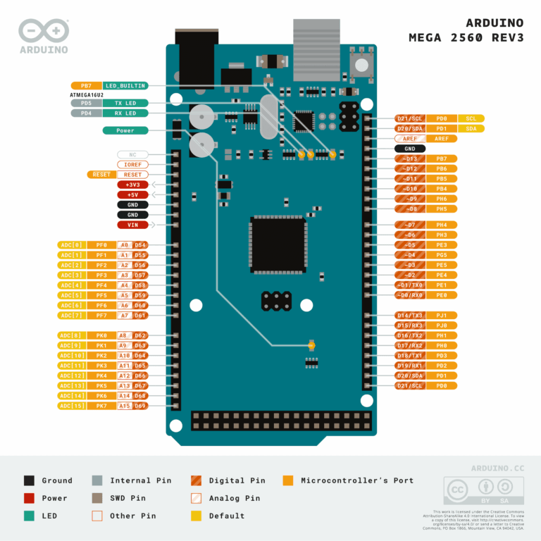
Monday, August 30, 2021

Arduino: Lesson 3 - Blinking an LED with delay() function

Fig. 1 - Arduino: Lesson 3 - Blinking an LED with delay()

Welcome to Lesson 3 - Basic Arduino Course

Today we are going to learn how to make our first algorithm, let's learn how to use the blink() function, this function makes your Arduino blink an LED, every time determined in the programming.

Hardware Required

  • Arduino Board
  • LED - optional "You can use the onboard LED"
  • 220 ohm resistor - optional "You can use the onboard resistor"

The Circuit

You can use as an example the built-in LED that most Arduino boards have. This LED is connected to a digital pin 13, however, this number may vary from board type to board type. 

This constant is LED_BUILTIN and allows you to control the built-in LED easily, and the correspondence of this constant is digital pin 13.

However, you can to lit an external LED with this sketch, you  only need to build the circuit showing in Figure 2 below, you can connect one external LED in serie with the resistor to the digital PIN 6

Connect the positive leg of the LED (the positive leg, is the anode) to the other end of the resistor. Connect the negative leg of the LED (the negative leg,  is the cathode) to the GND

Fig. 2 - Arduino Blink LED with delay function - tinkercad.com

Resistor calculation

We need to use a resistor in series with the LED to limit the current in the LED. The value of this resistor depends on the LED we will use.

Considering that we will use an external green LED, let us analyze this situation by following the steps below:

  • The power supply comes from a digital pin on the Arduino (Vdc = 5v). 
  • The LED needs a current of 20mA to be powered. 
  • And a supply voltage of 2.5V.

You can see the voltage requirements of LED in the table in Figure 3 below, which contains the average voltage of most standard color LEDs.

Fig. 3 - Typical Led Voltage Range

Knowing that the LED power supply is 2.5V and 20mA (0.02A), following the table in Figure 3, let's put the data already obtained in the formula in Figure 4 below, and calculate:

Fig. 4 - Formula to calculate the resistance for the power supply of LED

Formula: 

R = (Vps - Vled) / Iled

R = (5 - 2,5)/(0.02)

R = 125

As we can see, the result of the calculation made resulted in a resistance of 125Ω. As 20mA is on average the threshold value of the LED, R = 125Ω will also be its threshold resistance so as not to damage the LED.

The resistor value in series with the LED can be a different value, it can be one of 150 ohms, or more, such as 220 ohms, 330 ohms; the LED will also light up with higher values but with less intensity.

The Code

After building the circuit, connect your Arduino board to your computer, launch the Arduino Software (IDE), copy the code below and paste it into your Arduino IDE. But first, let's understand the code line by line. 

  • First, in void setup() structure, digital pin 6 is initialized as output pin, as shown in line 4 below 
1
2
3
4
5
// Arduino: Lesson 3 - Blinking an LED with delay()

void setup() {                      // This function is called once when the program starts pinMode(6, OUTPUT); // initialize digital pin 6 as an output.
}
  • In the void loop() structure, in line 8, the digitalWrite function, command activates port 6 to HIGH level, it means that it goes from 0V to 5V, which makes the LED receive the voltage and lit up. 
  • In the line 9, the delay() instruction indicates that we will have 1000 milliseconds or 1 second to wait, and then enters the next step which is to turn the LED off.
1
...
7
8
9
10
// Arduino: Lesson 3 - Blinking an LED with delay()

void loop() { // The loop structure runs over and over again forever digitalWrite(6, HIGH); // initialize digital pin 6 as an output.
delay(1000);           // Wait for 1 second
...

  • In the line 12, the digitalWrite function, command activates port 6 to LOW level, it means that it goes from 5V to 0V, Then turn the LED off.
  • In the line 13, the delay() instruction indicates that we will have 1000 milliseconds or 1 second to wait, and then enters the next step which is to turn the LED off.
1
...
7
...
12
13
// Arduino: Lesson 3 - Blinking an LED with delay()

void loop() { // The loop structure runs over and over again forever
digitalWrite(6, LOW); // initialize digital pin 6 as an output.
delay(1000);           // Wait for 1 second
...

This brings the LED pin back to 0 volts, and turns the LED off. Enough time should pass between powering on and powering off, that's long enough to see the LED blink. 

Therefore, the delay() function tell the Arduino board to do nothing for 1000 milliseconds or 1 second. When you use the delay() function, nothing else happens for that amount of time. 

The complete code is showed in the sketch below.

1
2
3
4
5
6
7
8
9
10
11
12
// Arduino: Lesson 3 - Blinking an LED with delay()

void setup() {                     // This function is called once when the program starts pinMode(6, OUTPUT); // initialize digital pin 6 as an output.
}

void loop() { // The loop function runs over and over again forever
digitalWrite(6, HIGH); // Turn the LED ON (HIGH voltage level)
delay(1000);           // Wait for 1 second
digitalWrite(6, LOW); // Turn the LED OFF (LOW voltage level)
delay(1000);                 // Wait for 1 second
}
//------------------------------------- www.elcircuits.com --------------------------------------------

We can also use the same code, adding a name to pin 6 of the code above, simply assigning an integer to pin 6.

1
2
3
4
// Arduino: Lesson 3 - Blinking an LED with delay()

int ledPin =  6;      // the number of the LED pin

In this way, you will use pin 6 identification as ledPin, as we can see in the complete code below.

1
2
3
4
5
6
7
8
9
10
11
12
13
14
15
// Arduino: Lesson 3 - Blinking an LED with delay()

int ledPin 6;      // The number of the LED pin

void
setup() {                              // This function is called once when the program starts pinMode(ledPin, OUTPUT);
// initialize digital pin 6 "ledPin" as an output.
}

void loop() { // The loop function runs over and over again forever
digitalWrite(ledPin, HIGH); // Turn the LED ON (HIGH voltage level)
delay(1000);           // Wait for 1 second
digitalWrite(ledPin, LOW); // Turn the LED OFF (LOW voltage level)
delay(1000);                           // Wait for 1 second
}
//------------------------------------- www.elcircuits.com --------------------------------------------

This second code will work the same way, however when we have many "Pins" ports in a larger project, and we need to change the pin to another port, in this second code, you simply change line 3 of the code, which assigns port 6, the integer ledPin to another port you need.

Next Lesson

Previous Lesson

If you have any questions, suggestions or corrections, please leave them in the comments and we will answer them soon.

Subscribe to our blog!!! Click here - elcircuits.com!!!

My Best Regards!!!

Sunday, August 22, 2021

Arduino: Lesson 2 - How to Install Arduino Software (IDE) on Windows - Step by Step!


Fig. 1 - Arduino: Lesson 2 - How to Install Arduino Software (IDE) on Windows - Step by Step!

Welcome to Lesson 2 - Basic Arduino Course

Today we are going to explain how to install Arduino Software (IDE) on Windows machines step by step. Let's get started!

STEP 1: First, download the latest version of the software here.
First of all, let's download the Arduino IDE from the official website arduino.cc, it's recommended to  get the latest version from the clicking on Download Page

Fig. 2 - How to Install Arduino IDE - Download Page

You can choose between the Installer (.exe) and the Zip packages how showing in Figure 2. We suggest you use the first one that installs directly everything you need to use the Arduino Software (IDE), including the drivers. 
Note: With the Zip package you need to install the drivers manually. The Zip file is also useful if you want to create a portable installation.

STEP 2: When the download has been completed, open the installer file and proceed with the installation, allow the driver installation process when you get a warning from the operating system and accept the License Agreement, how to showing in Figure 3 below.

Fig. 3 - How to Install Arduino IDE - Agreement Page

STEP 3: Select the folder where you want to install Arduino IDE, how to showing in Figure 4 below.

Fig. 4 - How to Install Arduino IDE - Folder location Select Page

STEP 4Choose the components to install and select all the components including the board drivers, how showing in Figure 5.
 
Fig. 5 - How to Install Arduino IDE - Check components Page

STEP 5: In some cases, we may get a “Windows Security” windows, how to showing in Figure 6 below, to install devices software, simply click on button “Install“, and wait until the installation completes.

Fig. 6 - How to Install Arduino IDE - Security Device Page

STEP 6: The process will extract and install all the required files to execute properly the Arduino Software (IDE). When finished, click in "Close" button, and the installation is finished.

Fig. 7 - How to Install Arduino IDE - Installation Page

That's it, you've just successfully installed the Arduino IDE Software on your computer!

If you have any questions, suggestions or corrections, please leave them in the comments and we will answer them soon.

Subscribe to our blog!!! Click here - elcircuits.com!!!

My Best Regards!!!

PinOut - ARDUINO Mega Rev3 Board - ATMega328PU

Fig. 1- Arduino Mega Rev3 Board - arduino.cc

The Arduino Mega 2560 is a microcontroller board based on the ATmega2560. It has 54 digital input/output pins (of which 15 can be used as PWM outputs), 16 analog inputs, 4 UARTs (hardware serial ports), a 16 MHz crystal oscillator, a USB connection, a power jack, an ICSP header, and a reset button.

Click here to Arduino Datasheet

Source: arduino.cc

If you have any questions, suggestions or corrections, please leave them in the comments and we will answer them soon.

Subscribe to our blog!!! Click here - elcircuits.com!!!

My Best Regards!!!

Monday, August 9, 2021

How to Make Cable; Guitar, Keyboard, Bass, Audio Mix, PA, among others, Step by Step!

DIY Audio Cables: Build Your Own Guitar, Keyboard, and Mixer Cables Step by Step

For Portuguese version, Click Here!

Hello Everyone!

Have you ever had trouble with incompatible audio cables or paid a lot for equipment you could have assembled yourself? In this complete guide you'll learn how to make your own professional audio cables for mixers, microphones, musical instruments, church sound systems, studios and more.

With exclusive diagrams and detailed instructions, you will master connections such as XLR, 1/4" (P10 / 1/4" TS/TRS), RCA and balanced cable wiring — saving money and customizing your audio setup safely and practically.

🛠️ Ready to Get Hands-On?

We’ll start with the most common, essential cables used daily by musicians and audio techs. After that we’ll move on to more specific and complex options.

1. 1/4" TS (Mono) — 1/4" TS (Mono) — For Instruments

The 1/4" TS (Tip-Sleeve) mono cable is one of the most used connectors in audio. It has two contacts (tip and sleeve) and is unbalanced. Its primary use is to connect instruments such as guitar, bass and keyboard to a mixer, amp or audio interface.

In live and recording contexts, this cable carries the instrument signal to the main sound system (PA — Public Address).

Figure 1 — 1/4" TS (mono) Male → 1/4" TS (mono) Male

1/4" TS (mono) male → 1/4" TS (mono) male
Fig. 1 – 1/4" TS (mono) male → 1/4" TS (mono) male

💡 Practical tip: Use good-quality 1/4" connectors and solid solder joints to avoid unwanted noise. Build your instrument cable with firm plugs and quality wire to prevent crackle and signal loss.

2. 1/4" TRS (Stereo/Balanced) → 2× 1/4" TS — Mixer Inserts

The 1/4" TRS (Tip-Ring-Sleeve) has three contacts and can be used as a balanced connection or to carry two separate mono signals.

On mixing consoles, TRS → dual TS cables are commonly used for insert connections, which send a channel’s signal to an external processor (compressor, EQ, effects) and return to the same channel.

Figure 2 — 1/4" TRS → 2× 1/4" TS

1/4" TRS → 2× 1/4" TS
Fig. 2 – 1/4" TRS → 2× 1/4" TS

💡 Practical tip: Mark send and return plugs with labels or colored heat-shrink to avoid swapping them during live shows.

3. XLR Female → 2× 1/4" TS — Converting Balanced Outputs

An XLR female to two 1/4" TS cable allows equipment with a balanced output (mixers, interfaces) to feed unbalanced inputs (amps, speakers).

XLR pinout:

  • Pin 1 = Ground (shield)
  • Pin 2 = Positive (hot)
  • Pin 3 = Negative (cold)

This cable splits a balanced signal into two independent mono channels.

Figure 3 — XLR female → 2× 1/4" TS

XLR female → 2× 1/4" TS
Fig. 3 – XLR female → 2× 1/4" TS

💡 Practical tip: Use this cable only when necessary. Whenever possible keep balanced-to-balanced (XLR ↔ XLR or TRS ↔ XLR) connections to reduce noise and interference, especially over long cable runs.

4. XLR Female → 1/4" TRS — Balanced Signals

An XLR female to 1/4" TRS cable is common for:

  1. Connecting a signal processor (EQ, compressor) with XLR output to an amplifier or active speaker with a TRS input.
  2. Feeding headphone amplifiers that offer XLR outputs (headphone distribution amplifiers).
  3. Carrying phantom power (+48V) for condenser microphones when required by the equipment design.

This cable preserves a balanced signal by using tip, ring and sleeve (tip = XLR pin 2, ring = XLR pin 3, sleeve = XLR pin 1).

Figure 4 — XLR female → 1/4" TRS

XLR female → 1/4" TRS
Fig. 4 – XLR female → 1/4" TRS

💡 Practical tip: Before connecting cables to equipment that provides phantom power, confirm the connected device supports it. This helps avoid damaging dynamic microphones or certain instruments.

5. XLR Female → 1/4" TS — Balanced to Unbalanced Adapter

This adapter is commonly used to connect balanced outputs (XLR) to unbalanced inputs (1/4" TS) — for example:

  • Connecting a professional microphone to a mixer or amplifier that only has a 1/4" input (common in simpler gear).
  • Feeding a balanced mixer/interface output to an amplifier or active speaker with a 1/4" TS input.

This connection adapts a 3-wire balanced signal to 2-wire unbalanced by discarding or tying the negative conductor (XLR pin 3) to ground, using only the positive (pin 2) and shield (pin 1) to the tip and sleeve of the TS plug.

Figure 5 — XLR female → 1/4" TS

XLR female → 1/4" TS
Fig. 5 – XLR female → 1/4" TS

💡 Practical tip: This wiring is useful in many practical situations, but whenever possible prefer fully balanced connections (XLR ↔ XLR or TRS ↔ XLR) to reduce noise and interference, especially over long cable runs.

6. XLR Male → 2× 1/4" TS — Splitting a Balanced Signal

This cable splits a balanced XLR male signal into two unbalanced 1/4" TS outputs (one per TS connector).

Practically it works as a splitter: sending the positive (pin 2) to one TS and the negative (pin 3) to the other. Use carefully because it does not replace a true stereo output and can introduce phase issues.

Figure 6 — XLR male → 2× 1/4" TS

XLR male → 2× 1/4" TS
Fig. 6 – XLR male → 2× 1/4" TS

💡 Practical tip: Useful for recording or testing but be mindful of phase and level issues — splitting like this is not a substitute for a true stereo source.

7. XLR Male → 1/4" TRS — Balanced XLR to TRS

This cable maps XLR male balanced pins to a 1/4" TRS balanced input: pin 2 → tip, pin 3 → ring, pin 1 → sleeve. It’s commonly used to connect balanced outputs to TRS inputs (for example, direct boxes and many interfaces).

Figure 7 — XLR male → 1/4" TRS

XLR male → 1/4" TRS
Fig. 7 – XLR male → 1/4" TRS

💡 Practical tip: This is one of the most used studio cables, letting you connect microphones or balanced mixer outputs directly to TRS inputs on audio interfaces.

8. XLR Male → 1/4" TS — Mixer/Interface to Amps or Speakers

The XLR male to 1/4" TS cable converts a balanced XLR output to an unbalanced TS input — used for amplifiers, active speakers and some instruments. Avoid long runs with this type of cable because you lose the benefits of a balanced line.

Figure 8 — XLR male → 1/4" TS

XLR male → 1/4" TS
Fig. 8 – XLR male → 1/4" TS

💡 Practical tip: Avoid long lengths in this configuration — the loss of balanced wiring can introduce noise.

9. XLR Female ↔ XLR Male — Balanced Microphone Cables

This is the classic microphone cable, used for balanced extensions and for connecting peripherals like active speakers, amplifiers, EQs and effects to the audio console.

Because it uses three conductors (ground, positive and negative), the XLR cable provides protection from noise and can be run much longer than unbalanced cables.

Figure 9 — XLR female → XLR male

XLR female → XLR male
Fig. 9 – XLR female → XLR male

💡 Practical tip: Invest in quality XLR cables if you plan to use condenser microphones or run long cable lengths.

10. 2× RCA → 1/4" TRS — Players, Mixers and DJ Gear

This cable converts two RCA signals (left and right) into one 1/4" TRS stereo plug. It is often used with DJ mixers, media players and receivers to feed a mixer or interface TRS input.

Figure 10 — 2× RCA → 1/4" TRS

2× RCA → 1/4" TRS
Fig. 10 – 2× RCA → 1/4" TRS

💡 Practical tip: Keep RCA runs short to reduce interference.

11. 2× RCA → 2× 1/4" TS — Split RCA to Two Mono TS

Here each RCA output (L/R) is wired individually to a TS plug. Useful in hybrid setups when connecting consumer audio sources (CD/DVD/players) to an audio system or active speakers with 1/4" inputs.

Figure 11 — 2× RCA → 2× 1/4" TS

2× RCA → 2× 1/4" TS
Fig. 11 – 2× RCA → 2× 1/4" TS

💡 Practical tip: Verify channel mapping (red = right, white = left).

12. 2× RCA → 2× RCA — Standard Stereo RCA

Standard stereo RCA cables are very common for home audio gear (CD, DVD, turntables, receivers) and some older mixers. They carry unbalanced left and right channels.

Figure 12 — 2× RCA → 2× RCA

2× RCA → 2× RCA
Fig. 12 – 2× RCA → 2× RCA

💡 Practical tip: Ideal for short distances only — for professional setups prefer balanced connections whenever possible.

📋 Summary Table — Common Audio Cable Types

Below are the main cables covered in this guide, their uses and quick tips.

Cable Connectors Main Use Signal Type Quick Tip
1 1/4" TS → 1/4" TS 2× 1/4" TS (male) Guitar, bass, keyboard Unbalanced Use short runs to avoid noise.
2 1/4" TRS → 2× 1/4" TS 1× TRS → 2× TS Insert / stereo split Unbalanced (or balanced if used as TRS) Good for headphone outs and keyboard stereo splits.
3 1/4" TRS → 1/4" TRS 2× TRS Headphones, stereo outputs Unbalanced / Balanced Avoid lengths over ~3 m for unbalanced signals.
4 XLR (F) → 1/4" TRS XLR F → TRS Mic or balanced out to TRS Balanced Maintains quality over long runs.
5 XLR (F) → 1/4" TS XLR F → TS Adapt XLR to TS input Unbalanced Use only when no balanced input is available.
6 XLR (M) → 2× 1/4" TS XLR M → 2× TS Split balanced to two TS Semi-balanced For tests only; watch for phase issues.
7 XLR (M) → 1/4" TRS XLR M → TRS Mic/mixer to TRS input Balanced Common in studios & interfaces.
8 XLR (M) → 1/4" TS XLR M → TS Mixer/interface to amp/speaker Unbalanced Prefer short runs.
9 XLR F → XLR M XLR F ↔ XLR M Microphone cables, extensions Balanced Professional standard; long distances OK.
10 2× RCA → 1/4" TRS 2× RCA → TRS DJ gear, players, domestic mixers Unbalanced Keep RCA runs short to avoid noise.
11 2× RCA → 2× 1/4" TS 2× RCA → 2× TS Adapt RCA players to TS inputs Unbalanced Verify channel mapping (L/R).
12 2× RCA → 2× RCA 2× RCA Home audio: CD, DVD, receivers Unbalanced Use for short distances only.

🧾 Conclusion

This guide covered everything from basic instrument cables (1/4" TS, RCA) to professional alternatives like balanced XLR and its variations. With the diagrams and tips you now know each cable’s purpose, correct wiring and the precautions to avoid noise and failures.

If you want to learn how to wire Neutrik combo connectors (XLR + 1/4" jack) used in many consoles and panels, check this related guide: How to Wiring the Neutrik Combined Connector.

💬 Which of these cables do you use most often?

Leave a comment below and share your experience — it can help other readers building their own cables!

If you have any questions, suggestions, or corrections, feel free to share them in the comments — we’ll be glad to help and improve this guide together!

👉 Stay updated with our latest electronic projects, tutorials, and DIY guides. Subscribe to ElCircuits and never miss a new post!

Best regards,
The ElCircuits Team ⚡