 |
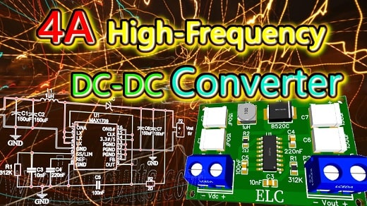
| Fig. 1 - 4A Low-Noise High-Frequency Step-Up DC-DC Converter using MAX1709 with PCB |
This is a DC-DC converter circuit that uses a MAX1709 series Integrated Circuit as the main component, it works with a Step-Up conversion system.
This powerful microcircuit is able to work with very few external components and deliver a fixed 3.3V or 5V or adjustable 2.5V to 5.5V voltage, with 4 Amperes of output current.
Integrated Circuit General Description
The MAX1709 sets a new standard of space savings for high-power, step-up DC-DC conversion. It delivers up to 20W at a fixed (3.3V or 5V) or adjustable (2.5V to5.5V) output, using an on-chip power MOSFET from a +0.7V to +5V supply.
Fixed-frequency PWM operation ensures that the switching noise spectrum is constrained to the 600kHz fundamental and its harmonics, allowing easy post filtering for noise reduction.
External clock synchronization capability allows for even tighter noise spectrum control. Quiescent power consumption is less than 1mW to extend operating time in battery-powered systems.
Two control inputs (ONA, ONB) allow simple push-on, push-off control through a single momentary push button switch, as well as conventional on/off logic control.
The MAX1709 also features programmable soft-start and current limit for design flexibility and optimum performance with batteries.
The maximum RMS switch cur-rent rating is 10A. For a device with a lower current rating, smaller size, and lower cost, refer to the MAX1708 datasheet.
You may be interested in:
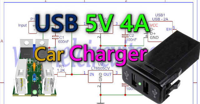
- Switched Power Supply SMPS 13.8V 10A using IR2153 IC and IRF840, with PCB
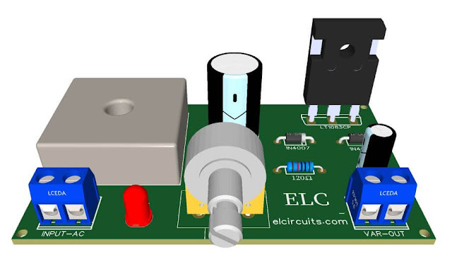
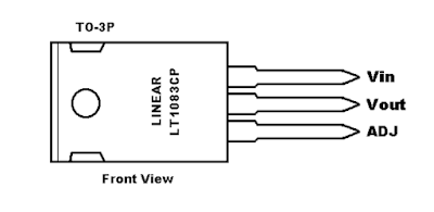
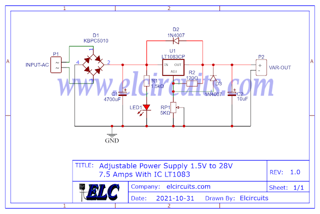
- Adjustable Power Supply 1.5V to 28V, 7.5 Amps With IC LT1083 + PCB
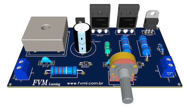
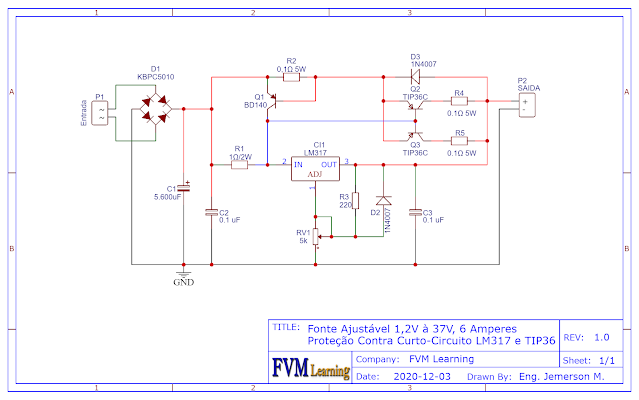
- Adjustable Power Supply 1.2V to 37V, 6A, Short Circuit Protection with LM317 and TIP36 + PCB
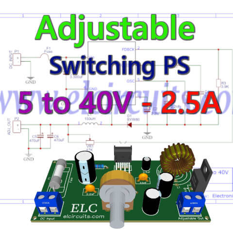
- Adjustable Switching Power Supply 5.1 to 40V, 2.5 Amp using L4960 + PCB
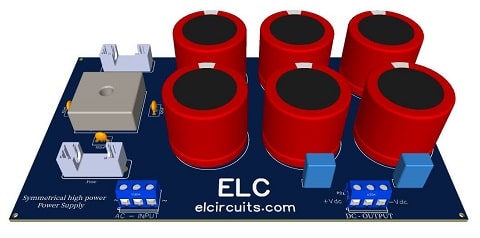
- Symmetrical Adjustable Power Supply 1.25V to 47V 10 Amps with Short Circuit Protection + PCB
- Adjustable Power Supply 1.25v to 57V, 6 Amps with TIP36C + LM317HV + PCB
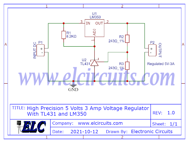
- Adjustable Power Supply 1.25v to 33V, 3 Amps with LM350 + PCB
- Stabilized Power Supply 13.8V High Current 10 Amps with PCB
The Circuit Schematic
In Figure 2, below, we can see the schematic diagram of 4A Low-Noise High-Frequency Step-Up DC-DC Converter using MAX1709.
The circuit is simple to assemble, there are few external components, and there is no need for adjustment, once assembled, it is ready to work, if everything is correct, of course!
The PCB tracks are bent, the main ones have their tracks at the bottom and at the top of the PCB, because the current is 4 amperes.
The capacitors are tantalum, however if you can't find them, electrolytic capacitors can be used, however for more sensitive circuits, the performance may not be as expected, but in most circuits they work very well.
The DC-DC converter supports input from 0.7V up to 5V, and at the output it maintains the stabilized voltage of 5V, however to get the promised 4 Amps, it is necessary to have at least 3.3V at the input.
 |
| Fig. 2 - Schematic Circuit 4A Low-Noise High-Frequency Step-Up DC-DC Converter using MAX1709 |
Components List
- Semiconductors
- U1 ...... MAX1709 SMD Integrated Circuit
- D1 ..... B520C SMD Schottky Diode 5A
- Resistor
- R1 ..... 312KΩ SMD resistor (orange, brown, red, orange, gold)
- R2 ..... 2Ω SMD resistor (red, black, black, gold)
- Capacitor
- C1, C2, C6, C7 ... 150uF SMD Tantalum Capacitor
- C3 ....................... 10nF SMD Ceramic Capacitor
- C4 ....................... 220nF SMD Ceramic Capacitor
- C5 ....................... 100nF SMD Ceramic Capacitor
- Miscellaneous
- L1 .......... 1uH 5A SMD Inductor
- P1, P2 .... 2-pin PCB soldering terminal blocks (Optional)
- Others .... Printed Circuit Board, wires, etc.
Printed Circuit Board
In Figure 3, we provide the PCB - Printed Circuit Board, in GERBER, PDF and PNG files. These files are available for free download, on the MEGA server, in a direct link, without any bypass.All to make it easier for you to do a more optimized assembly, either at home, or with a company that prints the board. You can download the files in the Download option below.
 | |
|
Files to download, Direct Link:
Click on the link beside: GERBER, PDF and PNG files
If you have any questions, suggestions or corrections, please leave them in the comments and we will answer them soon.
My Best Regards!!!