 Português
 Español
Simple 3-Transistor Power Amplifier for 600W RMS Subwoofer + PCB

Simple 3 Transistors Power Amplifier PCB
For Portuguese version, click here!
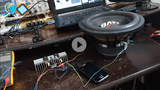
This is a simple amplifier that uses only 3 transistors, and has the ability to push a 600W RMS Subwoofer speaker with great mastery.
The circuit is quite simple, and easy to assemble, we took this circuit from our Brazilian partner FVM Learning, and this is their direct link www.fvml.com.
This mini amplifier was tested in two stages, one with 24V, with a non-symmetrical power supply, and in 30V also with non-symmetrical power, the result you can watch in the original video at the end of this post.
The Amplifier Circuit
The amplifier circuit is very simple to be arranged in figure 2 just below, it is divided into two stages:
- The first stage is the pre-amplification and at the same time used as a drive to boost the output stage. It is formed by a transistor medium power the BD139, which supports a voltage of up to 80V and a current of 1.5A with 12.5 W of power, according to the Datasheet of the same.
- The second is the power stage, which is formed by the complementary transistors NPN – 2SC5200 and the PNP – 2SA1943 transistor, with 100W of power and high fidelity, whose collector current supported is 15 Amps.

Fig. 2 – Simple 3 transistors Power Amplifier schematic diagram
You might also be interested in:
- 400W Class AB Amplifier using MJL4281A and MJL4302A transistors + PCB
- Simple 100W Power Amplifier with TIP142 NPN and TIP147 PNP transistors + PCB
- 200W RMS Power Amplifier With 2SC2500 AND 2SA1943 + PCB
- 300W RMS Power Amplifier – 2SC3858 and 2SA1494 Transistors + PCB
- 50W RMS Audio Amplifier with IRF530 and IRF9530 Mosfet + PCB
- 100W RMS Power Amplifier With 2 NPN 2SC5200 Transistors At Output + PCB
Note
Place the power transistors in a heat sink, especially if you are going to apply a voltage greater than 20V and use the amplifier continuously, they will heat up.
Component List
- T1 ———- NPN 2SC5200 Power complementary transistor
- T2 ———- PNP Complementary Power Transistor 2SA1943
- T3 ———- NPN BD139 transistor
- D1, D2 —– Diode 1N4007
- C1 ———- Electrolytic capacitor 2.200uF – 63V
- C2 ———- Electrolytic capacitor 4.7uF – 25V
- R1, R2 —– Resistor 0.22 ohms – 5W – (red, red, silver)
- R3 ———- Resistor 1k ohms – (brown, black, red)
- R4 ———- Resistor 100k ohms – (brown, black, yellow)
- P1 ———- 10K ohm potentiometer
- Others —– Wires, Welds and Etc.
Watch the original video of the FVML channel of the tests, and the assembly step by step, and be surprised !!!!
We are offering to download the link with the printed circuit board printing files, they are; Gerber, PDF layout, PNG, all the files with a direct link to Mega.
Direct link to download
Click in the link below to download the Files: PCB Layout, PDF, GERBER
Click Here!!!
✨ Our Gratitude and Next Steps
We sincerely hope this guide has been useful and enriching for your projects! Thank you for dedicating your time to this content.
Your Feedback is Invaluable:
Have any questions, suggestions, or corrections? Feel free to share them in the comments below! Your contribution helps us refine this content for the entire ElCircuits community.
If you found this guide helpful, spread the knowledge!
🔗 Share This Guide
Best regards,
The ElCircuits Team ⚡


