 Português
 Español
300W RMS Power Amplifier using 2SC3858 and 2SA1494 Transistors + PCB
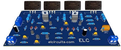
PCB 300W RMS Power Amplifier – 2SC3858 and 2SA1494 Transistors
This is a 300W RMS Power Amplifier using complementary power transistors 2SC3858 and 2SA1494, this circuit amplifier isn’t so simple to building, it will be necessary to have at least a little experience in electronics.
To set up this circuit, its complexity is moderate, but, if you haven’t skills in electronics circuits, we advise you not to do it, however, if you really want to do it, call someone with experience, to help you.
🔌 Schematic Diagram Circuit
This amplifier has an excellent audio quality, and use four output power transistors, it reaches a sound power of 300W RMS under load of 4 ohms, powered with a symmetric power supply. You can check the schematic diagram in Figure 2 below.
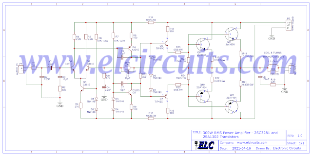
Fig. 2 – Schematic 300W RMS Power Amplifier – 2SC3858 and 2SA1494 Transistors
⚡ Power Supply
The power supply consists of a symmetrical transformer 45V – 0 – 45V center tape, 6 Amperes current supply, can be used. After rectified, we will have approximately 63Vcc at the output of the symmetrical power supply .
You might also be interested in:
- 400W Class AB Amplifier using MJL4281A and MJL4302A transistors + PCB
- Simple 100W Power Amplifier with TIP142 NPN and TIP147 PNP transistors + PCB
- 200W RMS Power Amplifier With 2SC2500 AND 2SA1943 + PCB
- 50W RMS Audio Amplifier with IRF530 and IRF9530 Mosfet + PCB
- 100W RMS Power Amplifier With 2 NPN 2SC5200 Transistors At Output + PCB
- Simple 3 Transistors Power Amplifier push a 600W RMS Subwoofer + PCB
🧾 Bill of Materials
- Q1, Q2, Q3, Q5 ……… C1815 NPN Transistor
- Q4 ………………………… A1015 PNP Transistor
- Q7 ………………………… TIP 42C PNP Transistor
- Q8, Q9 ………………….. 2SC3858 NPN Power Transistor
- Q10, Q11 ………………. 2SA1494 PNP Power Transistor
- Q6 ………………………… TIP41C NPN Transistor
- D1 to D7 ……………….. 1N4148 diode, or equivalent diode 1N4001
- C1, C4 ……………………. 2.2uF – 25V Electrolytic Capacitor
- C2 …………………………. 220pF Polyester / Ceramic Capacitor
- C8 …………………………. 100nF Polyester / Ceramic Capacitor
- R2, R10 ………………….. 47k ohms resistor (yellow, violet, orange, gold)
- R3, R5 ……………………. 2.2k ohms resistor (red, red, red, gold)
- R4 ………………………….. 270 ohms resistor (red, violet, black, gold)
- R6, R7 ……………………. 51K ohms – 1/2W resistor (green, brown, orange, gold)
- R8, R9, …………………… 100 ohms resistor (brown, brown, black, gold)
- R11 ………………………… 470 ohms resistor (yellow, violet, brown, gold)
- R12 ………………………… 390 ohms resistor (orange, white, brown, gold)
- R13, R14 ………………… 100 ohms – 2W resistor (brown, brown, black, gold)
- R17, R18 …………………. 6R8 ohms – 1W resistor (blue, gray, gold, gold)
- R15, R16, R19, R20 …. 100 ohms – 1W resistor (brown, brown, black, gold)
- R21, R22, R23, R24 …. 0.33 ohms – 5W resistor (orange, orange, gold, gold)
- R25 ………………………… 22 ohms resistor (red, red, black gold)
- R26 ………………………… 10 ohms – 1W resistor – (brown, black, black. gold)
- P1, P2 ……. 2 Pin – PCB Terminal Blocks – EK500V-XXP 20A – or equivalent
- P3 …………. 3 Pin – PCB Terminal Blocks – EK500V-XXP 20A – or equivalent
- L1 …………. 5uH – Air Core Coil 10 Turns 18AWG, 3/8″ Core
- Others …… Loudspeaker, Wires, Solders and Etc.
🖨️ Printed Circuit Board
We provide the PCB – Printed Circuit Board, in GERBER, PDF and PNG files. These files are available for free download, on the MEGA server, in a direct link, without any bypass.
All to make it easier for you to do a more optimized assembly, either at home, or with a company that prints the board. You can download the files in the Download option below.
📥 Files to download, Direct Link:
✨ Our Gratitude and Next Steps
We sincerely hope this guide has been useful and enriching for your projects! Thank you for dedicating your time to this content.
Your Feedback is Invaluable:
Have any questions, suggestions, or corrections? Feel free to share them in the comments below! Your contribution helps us refine this content for the entire ElCircuits community.
If you found this guide helpful, spread the knowledge!
🔗 Share This Guide
Best regards,
The ElCircuits Team ⚡


