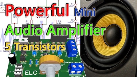
This is a simple amplifier that uses only 5 transistors, and provides good power, by our tests, we get close to 90W, and amazingly enough, it has a very good sound given its ultra simplicity.
The circuit is quite simple, and very easy to building, which makes it a great option for those who want to build an amplifier with good power and great cost, because it uses discrete components, cheap and easy to acquire.
🔌 The Amplifier Circuit
The amplifier circuit is very simple to assemble, as shown in Figure 2 just below, this amplifier is divided into three basic stages:
- The first is the pre-amplification stage: It is formed by a differential pair set of NPN 2N5551 transistors, they are working as differential pair, which gives a very good stability in the signal sent to the next stage.
- The second is the driver stage: it is formed by the PNP TIP42 transistor, it is used as a current amplifier and serves to drive the output stage.
- The third is the power stage: It is formed by a pair of differential power transistors, one is the NPN 2SC5200 and the other is the 2SA1943, they are in push-pull mode, configured to work in class AB, with base BIAS diodes.
 |
| Fig. 2 - Schematic diagram Powerful Mini Audio Amplifier using only 5 Transistors |
📌 Note
Place the power transistors on a heat-sink, because since you work with power, they will get hot, a small size radiator will help.
For those who like loud sound, to really force the amplifier to the maximum, it is recommended to put the BIAS diodes in series, on the heat sink along with the transistors. This will cause the base voltage to be controlled according to the temperature of the transistors.
You might also be interested in:
- Build a 50W RMS Audio Amplifier with Mosfet | Complete DIY Guide
- 160W High Fidelity Amplifier using Mosfet 2SK1058 and 2SJ162 with PCB
- 440W Class AB Power Amplifier using Mosfet IRFP9240 and IRFP240 with PCB
- 400W Class AB Amplifier using MJL4281A and MJL4302A transistors + PCB
- Simple 100W Power Amplifier with TIP142 NPN and TIP147 PNP transistors + PCB
- 200W RMS Power Amplifier With 2SC2500 AND 2SA1943 + PCB
- 300W RMS Power Amplifier - 2SC3858 and 2SA1494 Transistors + PCB
- 50W RMS Audio Amplifier with IRF530 and IRF9530 Mosfet + PCB
- 100W RMS Power Amplifier With 2 NPN 2SC5200 Transistors At Output + PCB
⚡Power Supply
The power is supplied through a 24 VAC transformer, after rectification the supply will provide 35 VDC. The current to power this amplifier is at least 3A, for those mounting two of these to form a stereo pair, you should double the current to 6 Amps.
The power is supplied through a 24 VAC transformer, after rectification the supply will provide 35 VDC. The current to power this amplifier is at least 3A, for those mounting two of these to form a stereo pair, you should double the current to 6 Amps.
🧾 Component List
- Semiconductor
- Q1, Q2 .......... 2N5551 NPN Transistor
- Q3 ................. PNP BD140 Transistor
- Q4 ................. 2SC5200 NPN Power complementary transistor
- Q5 ................. 2SA1943 PNP Power complementary transistor
- D1, D2, D3 ... 1N4007 Diode
- Resistors
- R1, R5 .......... 100K ohms Resistor - (brown, black, yellow, gold)
- R2 ................. 6K8 ohms Resistor - (blue, gray, red, gold)
- R3 ................. 620 ohms Resistor - (blue, red, brown, gold)
- R4.................. 4K7 ohms Resistor - (yellow, violet, red, gold)
- R6 ................. 1k5 ohms Resistor - (brown, green, red, gold)
- R7, R8 ........... 0.22 ohms - 5W Resistor - (red, red, silver, gold)
- P1 .................. 10K ohm potentiometer
- Capacitors
- C1 ................ 2.2uF Polyester / Ceramic Capacitor
- C2 ................ 47uF - 65V Electrolytic capacitor
- Miscellanies
- P1 ................. Screw Terminal Type 5mm 2-Pin Connector
- P2 ................. Screw Terminal Type 5mm 3-Pin Connector
- J1 .................. Set of male connectors 2-Pin (Optional)
- Other ............. PCB, Wires, Speaker, Heat Sink, etc.
🖨️ Printed Circuit Board (PCB)
In Figure 3, we provide the PCB - Printed Circuit Board, in GERBER, PDF and PNG files. These files are available for free download, on the MEGA server, in a direct link, without any bypass.
All to make it easier for you to do a more optimized assembly, either at home, or with a company that prints the board. You can download the files in the Download option below.
 |
| Fig. 3 - PCB - Powerful Mini Audio Amplifier using only 5 Transistors |
📥 Files to download, Direct Link:
Click on the link beside: GERBER, PDF and PNG files
👋 I hope you enjoyed it!!!
If you have any questions, suggestions or corrections, please leave them in the comments and we will answer them soon.
🙏 Subscribe to our blog!!! Click here - elcircuits.com!!!
My Best Regards!!!


Thank you very much for taking the time to post this. I am trying to learn a bit about building amps and right now it seems very daunting. It may take a while, but I will report back with how my attempts at this circuit go.
ReplyDeleteHi @JEREMY
DeleteThank you very much!
I look forward to feedback on your good results!
Regards!