Monday, October 18, 2021

5-Band Graphic Equalizer Circuit using LF353 IC + PCB

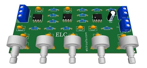
Fig. 1 - 5-Band Equalizer Circuit with LF353 IC

This 5 Band graphic equalizer circuit is based on the eight pins operational amplifier LF353 integrated circuit.

The LF353 is a two-input JFET operational amplifier with an internally compensated input offset voltage. The JFET input device provides wide bandwidth, low input bias currents and offset currents.

You might also be interested in:

Features

  • Internally trimmed compensated voltage: 10mV
  • Low input bias current: 50pA
  • Wide gain bandwidth: 4 MHz
  • High slew rate: 13V / μs
  • High input impedance: 1012Ω

The equalizer circuits

The proposed equalizer is a 2-octave graphic equalizer with a 5-band circuit, the cut-off frequencies are at: 50Hz, 200Hz, 800Hz, 3.2kHz and 12kHz.

This circuit was assembled with LF353, but nothing prevents you from using other replacement ICs, such as: LM1458, RC4558, etc.

The Power Supply

The power supply used for this circuit is symmetric, i.e.: +15V | 0V | -15V, with a direct current voltage DC.

The recommended supply voltage ranges between ±11V and ±15V, but note that the maximum voltage supported by the IC is ±18V.
The consumption current of the IC is 6.5mA maximum and 3.6mA on average.

The Circuit

The 5-band Equalizer uses three Integrated Circuits operational amplifier LF353, and the capacitors determine the frequencies, the higher their capacitance, the lower the cutoff frequencies.

Each IC has two internal amplifiers, we get an amplifier for each frequency and the last one for the final amplification of the entire circuit. In Figure 2 below, the pinout and configuration of the LF353 integrated circuit is shown.
Fig. 2 - Pinout IC LF353


In Figure 3 below, we show the complete 5-band equalizer circuit, and that you can download the files in option; Download files below at the bottom of the page.
Fig. 3 - Schematic Diagram 5-band Equalizer Circuit with LF353 IC

Components List

  • U1, U2, U3 .... LF353 Integrated circuit

  • R1  ................. 47K resistor (yellow, purple, orange, gold)
  • R2 to R11 ...... 10K resistor (brown, black, orange, gold)
  • R12 ................ 100K resistor (brown,  black, yellow, gold)

  • C1 ................... 680nF polyester capacitor
  • C2, C3 ............ 150nF polyester capacitor 
  • C4 ................... 33nF polyester capacitor
  • C5 ................... 39nF polyester capacitor
  • C6, C7 ............ 8.2nF polyester capacitor
  • C8, C9 ............ 2.2nF polyester capacitor
  • C10 ................. 470pF polyester capacitor
  • C11 ................. 4.7uF electrolytic capacitor

  • VR1 to VR5 ... 47K Potentiometer 

  • P1  .................. Screw Terminal Type 5mm 3-Pin Connector
  • P2, P3 ............. Screw Terminal Type 5mm 2-Pin Connector
  • Others ............. PCB, tin, wires, etc.

Download

We provide the files with the PCB, the schematic, the PDF, GERBER and JPG, PNG and provide a direct link for free download and a direct link, "MEGA".

Click on the direct link to download the files: Layout PCB, PDF, GERBER, JPG

If you have any questions, suggestions or corrections, please leave them in the comments and we will answer them soon.

Subscribe to our blog!!! Click here - elcircuits.com!!!

My Best Regards!!!

Sunday, October 17, 2021

Arduino: Lesson 8 - Using LDR Sensor and reading values on Serial Monitor


Fig. 1 - Using LDR Sensor and reading values on Serial Monitor

Welcome to Lesson 8 - Basic Arduino Course

In today's lesson, we will learn how to use an LDR sensor and read values on a Serial Monitor with Arduino. 

To measure light intensity, we will use the famous and widely used low-cost LDR (Light Dependent Resistor) sensor, to detect the intensity of light or darkness easily and cheaply.

LDR (Light Dependent Resistor) Sensor

LDR is a special type of resistor that passes higher voltage (low resistance) when light intensity is high and low voltage (high resistance) when darkness is low. 

With this method, we can use it for example in projects such as:

  • Lack of Light Alarm - Triggers an alarm when power is cut.
  • Brightness Control - Used to control the brightness of a recording or filming environment for example.
  • Contrast Control Screen - Often used on mobile phones to automatically lower or increase the brightness of the Display.
  • Emergency Light - Automatically turns on when Light is cut.
  • Ticket Counter - Also used to count people at the entrance of an establishment.
  • Invasion Alarm - Used to trigger an alarm when there is an invasion of the monitored establishment. 

In today's example, we will use this sensor to measure numerical resistance and read these values from the serial monitor.

To do this, we will use the Arduino analog Port A0. We can use any analog Port, in case of Arduino Uno there are 6 ports; A0 to A5.

Hardware Required

  • Arduino Board
  • LDR - Sensor Dependent Light
  • 100K ohms resistor - (Brown, black, yellow, gold)
  • Jumper Wires
  • Protoboard (optional)

The Circuit Connections

The circuit is very simple, we connect one leg of the LDR to positive 5V, and another leg to the 100K resistor in series with negative GND, and the same leg that takes the resistor and LDR, we connect to port A0, as shown in Figure 2 below.

Fig. 2 - Using LDR Sensor and reading values on Serial Monitor - tinkercad.com

We use a protoboard to facilitate the connections, but you can also connect the wires directly to the Arduino.

The Code

The analogReads() function, reads the value from the specified analog pin. Arduino boards contain a multichannel, 10-bit analog to digital converter. This means that it will map input voltages between 0 and the operating voltage(5V or 3.3V) into integer values between 0 and 1023

On an Arduino UNO, for example, this yields a resolution between readings of: 5 volts / 1024 units or, 0.0049 volts (4.9 mV) per unit

After building the circuit, connect your Arduino board to your computer, launch Arduino Software (IDE), copy the code below and paste it into your Arduino IDE. But first let us understand the code line by line. 

  • In Line 3, we declared sensorPin to select the analog input Pin A0 to connect the LDR.
  • In Line 4, we declared sensorValue as a variable to store the value coming from LDR sensor.

  • In Line 6we enter the void setup() function. This function is read only once when the Arduino is started.
  • In Line 7, we sets the serial port for communication, we will read the numeric value from LDR sensor. 
1
2
3
4
5
6
7
8
9
// Arduino Lesson 8 - Using LDR Sensor and reading values on Serial Monitor with Arduino

int sensorPin = A0;        // Select the Analog input pin for LDR
int sensorValue = 0;       // Variable to store the value coming from the sensor

void setup() {                // This function is called once when the program starts
 Serial.begin(9600);       // Sets Serial Port for communication with bounce rate in 9600
}
//------------------------------------- www.elcircuits.com --------------------------------------------
  • In Line 10, we enter in the loop() function does precisely what its name suggests, and loops consecutively.

  • In Line 11, the sensorValue variable, receives the value read from sensorPin, which is the analog input Pin, and stores the read values.

  • In Line 12, the Serial.println() function, prints the values from the variable sensorValue on the serial monitor screen.
1
...
10
11
12
13
14
// Arduino Lesson 8 - Using LDR Sensor and reading values on Serial Monitor with Arduino

void loop() { // The loop function runs over and over again as long as the Arduino has power.
sensorValue = analogRead(sensorPin);    // Read the value from the sensor
Serial.println(sensorValue);                      // Prints the values coming from the sensor on the Serial Monitor
}
//------------------------------------- www.elcircuits.com --------------------------------------------
Below you can see the full code, which we can be copying and pasting into your Arduino IDE, and uploading to Arduino.

The complete code is showed in the sketch below!

1
2
3
4
5
6
7
8
9
10
11
12
13
14
// Arduino Lesson 8 - Using LDR Sensor and reading values on Serial Monitor with Arduino

int sensorPin = A0;        // Select the Analog input pin for LDR
int sensorValue = 0;       // Variable to store the value coming from the sensor

void setup() {               // This function is called once when the program starts  
 Serial.begin(9600);      // Sets Serial Port for communication with bounce rate in 9600
}

void loop() { // The loop function runs over and over again as long as the Arduino has power.
sensorValue = analogRead(sensorPin);     // Read the value from the sensor
Serial.println(sensorValue);                       // Prints the values coming from the sensor on the Serial Monitor
}
//------------------------------------- www.elcircuits.com --------------------------------------------

All ready! After you have assembled the entire circuit, and uploaded this code, open the Serial Monitor and what you will see is the numerical value of the LDR.

When you approach the hands of the LDR inhibiting the Light, the number will drop to the minimum possible, it will depend on the LDR, and when you shine a light on the sensor, the number will go to the maximum of the sensor.
With that, the possibilities are immense, to work with this sensor.

Next Lesson

Previous Lesson

If you have any questions, suggestions or corrections, please leave them in the comments and we will answer them soon.

Subscribe to our blog!!! Click here - elcircuits.com!!!

My Best Regards!!!

Tuesday, October 12, 2021

180W RMS 4-Channel Amplifier using TDA7386 + PCB

Fig 1 - 180W RMS 4-Channel Amplifier with TDA7386 PCB

Para versão em Português, Clique Aqui!!!

The TDA7386 four-output integrated circuit is a class AB amplifier rated at 180W RMS "unbalanced power supply" in a single package with few external components.

This audio amplifier is designed for Sony®, Kenwood®, Pioneer® and other high performance car radios.

Features

  • High output power capacity:
  • 4 x 45W / 4Ω max.
  • 4 x 28W / 4Ω @ 14.4V, 1KHz, 10%.
  • 4 x 24W / 4Ω @ 13.2V, 1KHz, 10%
  • Low distortion
  • Low output noise
  • Stand-by function
  • Mute function
  • Auto- mute function when minimum supply voltage is detected
  • Low number of external components:
  • Internal fixed gain (26dB)
  • No external compensation
  • No bootstrap capacitors

You might also be interested in:


Based on the TDA7386 IC, it is also ideal for use in home studio amplifiers, computers with quadraphonic sound cards such as SoundBlaster Live! Creative Labs Inc. or MosterSound Diamond Multimedia / S3, Active Box, home theater, etc...

Each channel of the TDA7386 provides 45W RMS with a sufficient power of 14.4 volts, at a load of 4 ohms and a distortion factor of about 10%.

The amplifier schematic shown in Figure 2 is a simple design with few external components, making it an easy amplifier to build.
Fig. 2 - 180W RMS 4-Channel Amplifier with TDA7386 Schematic

Components List

  • IC 1 ..................... Integrated circuit TDA7386
  • R1  ...................... 47K resistor (yellow, purple, orange)
  • R2  ...................... 10K resistor (brown, black, orange)
  • C1, C2  ............... 1μF electrolytic capacitor
  • C3 ....................... 100nF electrolytic capacitor
  • C4  ....................... 220μF electrolytic capacitor
  • C5, C6, C7, C8  ....100nF electrolytic capacitor
  • C9  ....................... Electrolytic capacitor 470nF
  • C10  ..................... Electrolytic capacitor 47μF
  • B1  ....................... 2-Pin Board-Cable Connector
  • B2 ........................ 5-Pin Board-Cable Connector
  • B3, B4, B5, B6  ... 2-pin board cable connector
  • Others .................. PCB, tin, wires, etc.

Power supplies

For lovers of amplifiers with IC, it is best to have a simple power supply, because many have simple variable test bench sources that make testing much easier, in addition to an audio amplifier power for the car, we will necessarily have the simple power supply.

Since this amplifier operates at low voltage, the consumption is quite high. According to Ohm's law, we can calculate this current as follows, using the formula.
P = V * I

Where;
  • P = power, V = voltage, I = current.
Soon;
  • I = P / V
  • I = 180/14.4
  • I = 12.5 A
Due to the high current consumption indicated in the above formula, the connections to ground and to the power supply must be made with extreme care.

In car radios, the heat sink is small, but it is in contact with the radio housing, which is made of metal, which greatly facilitates heat dissipation.

For home amplifiers, which are usually in constant use, a good heat sink should be used. "It depends on how you are going to use it," you say, putting a cooler on the heatsink like the ones used in ATX computers.

Download

We provide the files with the PCB, the schematic, the PDF, GERBER and JPG, PNG and provide a direct link for free download and a direct link, "MEGA".

Click on the direct link to download the files: Layout PCB, PDF, GERBER, JPG


If you have any questions, suggestions or corrections, please leave them in the comments and we will answer them soon.

Subscribe to our blog!!! Click here - elcircuits.com!!!

My Best Regards!!!

Sunday, October 10, 2021

Arduino: Lesson 7 - Controlling LED Through Serial Monitor with Arduino


Fig 1 - Arduino: Lesson 7 - Controlling LED Through Serial Monitor with Arduino

Welcome to Lesson 7 - Basic Arduino Course

In today's lesson we will learn how to control the state of a LED via the Serial Monitor using the Arduino IDE.

We will use the Serial.readString() function which will cause the Arduino to interpret the sentence you have entered into the serial monitor, e.g. "Turn on the led". If you press ENTER Key in you computer, the LED will be turned on, if you want to turn off the LED just write the message "Turn off the LED".

With this method we can use it in different projects such as:

  • Load activation - Turns one or more loads on or off using commands.
  • Motor Speed Control - Use Serial Monitor to send the speed at which a PWM motor should run.
  • Calibrate a sensor's constant - We can create software to change a sensor's constant to a specified value if needed.

In our example today, we are using the serial monitor to trigger a LED, but you can also use a relay module to drive a motor, for example.

To do this, we will use the D9 digital port on Arduino. We can use any digital port we want. Just change the port you want to use in the declaration or the one that is available on your Arduino.

Required hardware

  • Arduino board
  • LED - Light Emitter Diode 220 Ohm Resistor - (red, red, brown, gold)
  • Jumper wires
  • Protoboard (optional)

The circuit

The circuit is quite simple. We connect a LED in series with a 220 ohm resistor to limit the current in the LED as we learned in previous lessons, and we connect the 9-port of the Arduino UNO as shown in Figure 2 below.

Fig. 2 - Controlling LED Through Serial Monitor with Arduino - tinkercad.com

We use a protoboard to facilitate the connections, but you can also connect the wires directly to the Arduino.

The code

The Serial.readString() function reads characters from the serial buffer and moves them to a given string.

In our example, we want to do something very simple, which is to turn on and off a LED using the command from Serial Monitor.

After building the circuit, connect your Arduino board to your computer, run the Arduino software (IDE), copy the code below and paste it into your Arduino IDE.

But first let us understand the code line by line.

  • In Line 3, we declared ledPin to digital Pin 9 where we connect the LED to the digital Pin 9
  • In Line 4, we declared the DataIn String that will receive the Serial Monitor Commands
  • In Line 6we enter the void setup() function. This function is read only once when the Arduino is started.
  • In Line 7, we begin serial communication by declaring the Serial.begin() function. At 115200 bits of data per second, this is the speed at which your computer will communicate with your Arduino Serial.
  • In Line 8, we define Port 9 as the output, using the pinMode(); function;
1
2
3
4
5
6
7
8
9
// Arduino: Lesson 7 - Controlling LED Through Serial Monitor with Arduino

int ledPin = 9;                                    // LED connected to digital pin 9
String DataIn;                                    // String that will receive the commands

void setup() {                                    // This function is called once when the program starts
Serial.begin(115200);                       // Begin the Serial Monitor with bounce rate in 115200
pinMode(ledPin, OUTPUT);            // Set the digital pin as output:
}
//------------------------------------- www.elcircuits.com --------------------------------------------
  • In Line 11, we enter in the void loop() function does precisely what its name suggests, and loops consecutively.
  • In Line 12, we enter in a if conditional, for to check if the Serial Monitor is available, if yes we call the next function.
  • In Line 13, we call the Serial.readString() function to read the characters from the Serial Monitor and send them to the String DataIn.

  • In Line 15we enter the if conditional, in this case to compare if the characters are the same as written in the Serial Monitor, in our example "turn led on", if yes...
  • In Line 16, we enter the digitalWrite function, command activates ledPin to HIGH level, it means that it goes from 0V to 5V, which turn the LED On.

  • In Line 17, we enter the if conditional, that compare if the characters are the same as written in the Serial Monitor, in our example "turn led off", if yes...
  • In Line 18, we enter the digitalWrite function, command desable ledPin to LOW level, it means that it goes from 5V to 0V, which turn the LED Off.
1
...
11
12
13
14
15
16
17
18
19
20
21
// Arduino: Lesson 7 - Controlling LED Through Serial Monitor with Arduino

void loop() { // The loop function runs over and over again as long as the Arduino has power
  if (Serial.available()) {                   // Check if there is any data on the serial monitor
    DataIn = Serial.readString();       // String DataIn receives the data typed in the Serial Monitor
  }
 if (DataIn == "turn led on") {          // Check if the received String is equal to "turn led on"  
    digitalWrite(ledPin, HIGH);         // If yes, the function digitalWrite turn Led ON
  } if (DataIn == "turn led off") {     // Check if the received String is equal to "turn led off" 
    digitalWrite(ledPin, LOW);         // If yes, the function digitalWrite turn Led OFF 
  }
}
//------------------------------------- www.elcircuits.com --------------------------------------------

B
elow you can see the full code, which we can be copying and pasting into your Arduino IDE, and uploading to Arduino.

The complete code is showed in the sketch below!

1
2
3
4
5
6
7
8
9
10
11
12
13
14
15
16
17
18
19
20
21
// Arduino: Lesson 7 - Controlling LED Through Serial Monitor with Arduino

int ledPin = 9;                                    // LED connected to digital pin 9
String DataIn;                                    // String that will receive the commands

void setup() {                                    // This function is called once when the program starts  
Serial.begin(115200);                       //Begin the Serial Monitor with bounce rate in 115200
pinMode(ledPin, OUTPUT);            // Set the digital pin as output:
}

void loop() { // The loop function runs over and over again as long as the Arduino has power
  if (Serial.available()) {                   // Check if there is any data on the serial monitor
    DataIn = Serial.readString();       // String DataIn receives the data typed in the Serial Monitor
  }
 if (DataIn == "turn led on") {          // Check if the received String is equal to "turn led on"  
    digitalWrite(ledPin, HIGH);         // If yes, the function digitalWrite turn Led ON
  } if (DataIn == "turn led off") {     // Check if the received String is equal to "turn led off" 
    digitalWrite(ledPin, LOW);         // If yes, the function digitalWrite turn Led OFF 
  }
}
//------------------------------------- www.elcircuits.com --------------------------------------------

Next Lesson

Previous Lesson

If you have any questions, suggestions or corrections, please leave them in the comments and we will answer them soon.

Subscribe to our blog!!! Click here - elcircuits.com!!!

My Best Regards!!!