Showing posts with label Amplifier. Show all posts

Tuesday, February 8, 2022

440W Class AB Power Amplifier using Mosfet IRFP9240 and IRFP240 Transistors with PCB


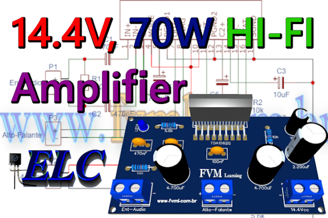
Fig. 1 - 440W Class AB Power Amplifier using Mosfet IRFP9240 and IRFP240 Transistors with PCB


This is a high performance power amplifier, which despite its simplicity in construction, in the tests performed, it presented parameters with great results, very close to what we call a HI-FI amplifier.

The Circuit Works

The complexity of the circuit is at an advanced level, it is not recommended for those who don't have experience in electronics and in assembling amplifier circuits, you must have minimal knowledge at an advanced level to assemble this type of power amplifier.

You might also be interested in:

The circuit diagram of the power amplifier is shown in Figure 2 below. It uses 8 output Mosfet power transistors, 4 transistors for the positive cycle and 4 transistors for the negative cycle. 

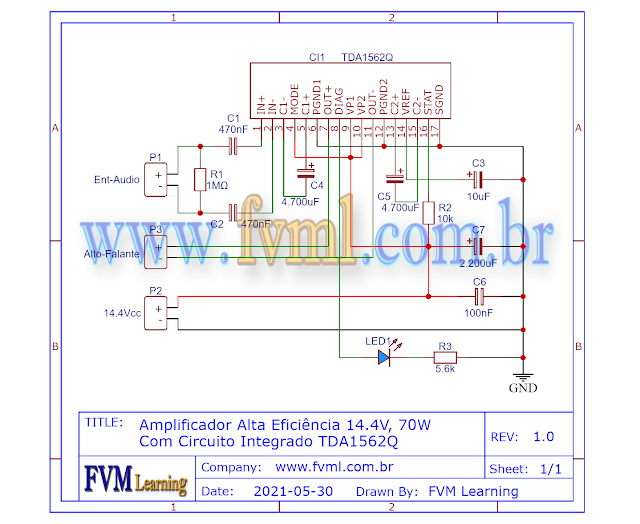
Fig. 2 - Schematic diagram 440W Class AB Power Amplifier using Mosfet IRFP9240 and IRFP240 Transistors 

The input circuit consists of a TL431 Op-Amp, it is used as a feed-forward preamplifier for the driver circuit units that produce a primary voltage gain at the output stage.

The circuit is divided into 2 identical half-cycles: one side for the positive half-wave of the signal fed through driver transistor Q1 NPN BD139, which feeds the output transistors (Q3, Q5, Q7, Q9 ) P-Channel IRFP9240, the other side for the negative half-wave of the signal fed through driver transistor Q2 PNP BD140, which feeds the output transistors (Q4, Q6, Q8, Q10) N-Channel IRFP240.

The Power Supply 

The power supply is of the symmetrical type, with a supply voltage of +55V | 0V | -55V, with a current of 10 Amperes, with good filtering. 

In Figure 3 below, we have a suggestion for a power supply that we use in our projects. In this article, besides having the schematic diagram with the Printed Circuit Board, you will understand how to easily calculate your own Power Supply, with the desired voltage.

You can in the link below:

Fig. 3 - Symmetrical Power Supply for Power Amplifiers

Components List

  • Semiconductors
    • U1 .......................... TL071 Integrated Circuit
    • Q1 .......................... BD139 NPN Transistor
    • Q2 .......................... BD140 PNP Transistor
    • Q3, Q4, Q5, Q6 ..... IRFP9240 Mosfet Transistor
    • Q7, Q8, Q9, Q10 ... IRFP240 Mosfet Transistor
    • D1, D2 ................... 1N4744 15V Zener diode
      D3, D4 ................... 1N4148 diode

  • Resistor
    • R1, R33 ................. 47KΩ (yellow, violet, orange, gold
    • R2 .......................... 1KΩ  (brown, black, red, gold)
    • R3, R4 .................... 2K7Ω (red, violet, red, gold)
    • R5, R6 .................... 2KΩ (red, black, red, gold)
    • R7 ........................... 6k8Ω Trimpot 
    • R8, R9 .................... 22KΩ (red, red, orange, gold)
    • R10, R11 ................ 33Ω (orange, orange, black, gold)
    • R12, R13 ................ 220Ω (red, red, brown, gold)
    • R14, R5 .................. 820Ω ( grey, red, brown, gold)
    • R16 ......................... 3.3Ω (orange, orange, gold, gold)
    • R17, R18, R21, R22, R25, R26, R29, R30 .... 39Ω (orange, white, black, gold)
    • R19, R20, R23, R24, R27, R28, R31, R32 .... 5W 0.33Ω (orange, orange, silver, gold)
  • Capacitor
    • C1, C5 .................... 100pF Ceramic Capacitor
    • C2, C6, C7 .............. 1uF Ceramic Capacitor
    • C3, C4, C9, C10 ..... 470uF / 65V Electrolytic Capacitor 
    • C8 ........................... 100nF Ceramic Capacitor


  • Miscellaneous 
    • P1 .......... 2-pin PCB soldering terminal blocks
    • P2 .......... 3-pin PCB soldering terminal blocks
    • Others .... Printed Circuit Board, heat sink, wires, etc.


We are offering the PCB - Printed Circuit Board, in GERBER, PDF and PNG files, for you who want to do the most optimized assembly, either at home, or if you prefer in a company that develops the board, you can is downloading and make the files in the Download option below.
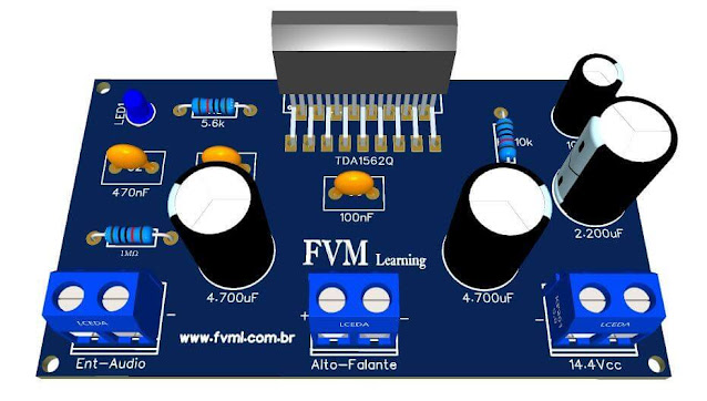
Fig. 3 - 440W Class AB Power Amplifier using Mosfet IRFP9240 and IRFP240 Transistors

Files to Download, Direct Link:

Click on the link beside: GERBER, PDF and PNG files

If you have any questions, suggestions or corrections, please leave them in the comments and we will answer them soon.

Subscribe to our blog!!! Click Here - elcircuits.com!!!

My Best Regards!!!


Monday, January 24, 2022

14.4V, 70W High Efficiency Power Amplifier using TDA1562Q IC + PCB

Fig. 1 - 14.4V, 70W High Efficiency Power Amplifier using TDA1562Q IC + PCB

The original project: Click Here!

This is a high efficiency and high power amplifier, powered by a simple 14.4V power supply, can provide a power of 70W in , using the TDA1562Q Integrated Circuit.

The TDA1562Q IC is a monolithic Class H power amplifier in Bridge-Tied Load (BTL) mode in a 17-lead DIL-folded-SIL plastic package.

The device can be used for general-purpose audio systems, however, given its low operating voltage, between 8V and 18V.

We can use it in: Car Sound, Subwoofer Boxes, as well as applications powered by a DC power supply connected to the mains, such as: speaker system, guitar amplifier, TV Sound, or in portable audio like Boombox, Etc.

Features

  • Very high output power, operating from a single low supply voltage
  • Low power dissipation, when used for music signals
  • Switches to low output power at too high case temperatures
  • Few external components
  • Fixed gain
  • Differential inputs with high common mode rejection
  • Mode select pin (on, mute and standby)
  • Status I/O pin (class-H, class-B and fast mute)
  • All switching levels with hysteresis
  • Diagnostic pin with information about:–  Dynamic Distortion Detector (DDD)–  Any short-circuit at outputs–  Open load detector–  Temperature protection.
  • No switch-on or switch-off plops

The Schematic

In Figure 2 below we have the schematic diagram of the High Efficiency Power Amplifier circuit and we can follow and analyze all the simplicity of the circuit, and as we can see, it is a circuit of easy assembly, and with few external components.

Fig. 2 - Schematic 14.4V, 70W High Efficiency Power Amplifier using TDA1562Q IC

Power Supply

This amplifier is powered by a simple positive and negative voltage type power supply, and has a supply voltage range that varies with a minimum voltage of 8V and a maximum voltage of 18V, the typical unstressed working voltage of the Integrated Circuit is 14.4V

The power supply should have a current of at least 5 Amperes, to be used in mono mode, if mounting in the stereo, "two channel" version, the current should be doubled, and should also be provided with good filtering to avoid ripples in the system, which can cause noise in the amplifier.

The impedance of this amplifier to reach its full power is , however we can set it to , however we will not get the maximum power of the amplifier.

Component List

  • Semiconductors
    • CI1 ............ TDA1562Q Integrated Circuit 
    • LD1 ........... LED Light Emitting Diode

  • Resistors
    • R1 .............. 1MΩ resistor (brown, black, green, gold)
    • R2 .............. 10KΩ resistor (brown, black, orange, gold) 
    • R3 .............. 5.6KΩ resistor (green, blue, orange, gold)  

  • Capacitors
    • C1, C2 ....... 470nF Ceramic / Polyester Capacitor
    • C3 .............. 10uF / 63v Electrolytic Capacitor
    • C4, C5 ....... 4700uF / 25V Electrolytic Capacitor
    • C6 .............. 100nF Ceramic / Polyester Capacitor
    • C7 .............. 2.200uF / 25V Electrolytic Capacitor

  • Others
    • P1, P2, P3 ... Screw Terminal Type 5mm 2-Pin Connector
    • Others ......... Heat sink for IC, wires, connectors, PCB, tin etc.

Printed Circuit Board

In Figure 3, we provide the PCB - Printed Circuit Board, in GERBER, PDF and PNG files. These files are available for free download, on the MEGA server, in a direct link, without any bypass. 

All to make it easier for you to do a more optimized assembly, either at home, or with a company that prints the board. You can download the files in the Download option below.

Fig. 3 -  PCB 14.4V, 70W High Efficiency Power Amplifier using TDA1562Q IC


Files to Download, Direct Link:

Click on the link beside: GERBER, PDF and PNG files

If you have any questions, suggestions or corrections, please leave them in the comments and we will answer them soon.

Subscribe to our blog!!! Click Here - elcircuits.com!!!

My Best Regards!!!


Friday, January 21, 2022

170W AB Class Bridge Mode Amplifier using TDA7294 IC + PCB

Fig. 1 - 170W AB Class Bridge Mode Amplifier using TDA7294 IC + PCB

Para Versão em Português, Clique Aqui!

This is a Class AB Audio Power Amplifier, it uses two TDA7294 Integrated Circuits, in Bridge Mode to drive one or more power speakers.

The circuit provides a total output power of 170W, and this with good sound quality, powered from a symmetrical power supply.

The Amplifier responds very well to all audible frequency ranges, and has a minimalist, compact design, which makes this amplifier a good choice for an unprecedented range of application. 

IC Description

The TDA7294 is  a monolithic integrated circuit in Multiwatt15  package, intended  for  use  as  audio class   AB   amplifier   in   Hi-Fi   field   applications (Home Stereo, self powered loudspeakers, guitar amplifier, Top-class TV). 

Thanks to the wide voltage range and to the high out current capability it is able to supply the highest power into both 4Ω and 8Ω loads even in  presence of  poor supply regulation, with high Supply Voltage Rejection.

The  built  in  muting  function  with  turn  on  delay simplifies the remote operation avoiding switching on-off noises.

You might also be interested in:

The main Advantages offered by Bridge solution

  • High power performance with voltage level limiting supply.
  • Considerably high output power, even at high load values (i.e. 16 Ohm).
  • For a Speaker with 8Ω, Vs = ± 25V, the maximum output power obtained is 150 W, while with a Speaker with 16Ω, Vs = ± 35V, the maximum power is 170 W.

Features

  • Operating Voltage Range (± 10V to ±40V)
  • DMOS Output Stage
  • High Output Power (Up to 100W musical)
  • Muting / Stand-By Functions
  • No Switch On/Off Noise
  • No Boucherot Cells
  • Very Low Distortion
  • Very Low noise 
  • Short-circuit protection
  • Thermal shutdown

Bridge Application

Our amplifier is configured in Bridge mode, where two TDA7294s ICs are used. With this type of configuration we get a pretty significant 170W of power, however there are two different configurations: 

For 8Ω Speaker - Vs = ± 25V, the maximum output power is 150 W.
For 16Ω Speaker - Vs = ± 35V, the maximum power is 170 W.

We know that the TDA7294, supports or speakers in mono version, however, for this application in Bridged configuration, the speaker impedance shouldn't be less than for reasons of dissipation and current carrying capacity of the Integrated Circuits.

The Schematic Circuit

In Figure 2 below we have the arrangement of the components of the amplifier circuit with the two TDA7294 ICs, and as we can see, the difficulty is not extreme.

Since there are few external components, making the amplifier circuit very simple to assemble, and a technician or hobbyist with average experience can assemble it without much difficulty. 

It is important to remember to be careful when assembling the circuit, not to invert any component such as capacitor diodes, or even when connecting the symmetrical voltage of the power supply.

Not to invert the voltage poles, because the integrated circuit or other components can be damaged.

Fig. 2 - Schematic 170W Amplifier Circuit in Bridge with Integrated Circuit TDA7294

Components List

  • Semiconductors
    • U1, U2 ........................ TDA7294 Integrated Circuit 
    • D1 ............................... 1N4148 Silicon Diode

  • Resistors
    • R1, R5, R6, R8, R10 ... 22K Resistor (red, red, orange, gold)
    • R2 ................................ 20K resistor (red, black, orange, gold)
    • R3 ................................ 10K resistor (brown, black, orange, gold)
    • R4 ................................ 30K resistor (orange, black, orange, gold)
    • R7, R9 ......................... 680Ω resistor (blue, gray, black, gold)

  • Capacitors
    • C1, C4 ......................... 1μF Ceramic/Polyester Capacitor
    • C2, C3, C5, C6 ............ 22μF Electrolytic Capacitor

  • Others
    • P1, P2 ......................... Screw Terminal Type 5mm 2-Pin Connector
    • P3 ................................ Screw Terminal Type 5mm 3-Pin Connector
    • J1 .................................Set of male connectors 3-Pin (Optional)
    • Other ........................... PCB, Wires, Speaker, etc.

Power Supply

The power supply will depend on which output power you will choose, which will also depend on how many Ohms your speaker will have. We have two versions:

Version 1 - 150W output.

  • Speaker must be 8Ω and the maximum voltage is for ±25V

Version 2 - 170W output.

  • Speaker must be 16Ω and the maximum voltage is ±35V.

Remember that for both versions a Symmetrical power supply is used, i.e. [ +VCC | GND | -VCC ]. With a current of at least 6 Amperes.

Printed Circuit Board

In Figure 3, we provide the PCB - Printed Circuit Board, in GERBER, PDF and PNG files. These files are available for free download, on the MEGA server, in a direct link, without any bypass. 

All to make it easier for you to do a more optimized assembly, either at home, or with a company that prints the board. You can download the files in the Download option below.

Fig. - PCB 170W AB Class Bridge Mode Amplifier using TDA7294 IC

Files to download, Direct Link:

Click on the link beside: GERBER, PDF and PNG files

If you have any questions, suggestions or corrections, please leave them in the comments and we will answer them soon.

Subscribe to our blog!!! Click Here - elcircuits.com!!!

My Best Regards!!!

Tuesday, January 11, 2022

HI-FI 120W RMS Amplifier Circuit using LM4780 IC + PCB

Fig. 1 - HI-FI 120W RMS Amplifier Circuit using LM4780 IC

This is a HI-FI Audio Amplifier circuit with high quality with a large frequency response, using the Integrated Circuit LM4780 which is a stereo audio amplifier. 

Capable of providing normally 60W per channel of average power of continuous output on an load with less than 0.5% THD + N from 20Hz to 20kHz.

LM4780 General Description

The LM4780 is fully protected utilizing National’s Self Peak Instantaneous TemperatureKe) (SPiKeTM) protection circuitry. 

SPiKe provides a dynamically optimized Safe Operating Area (SOA). SPiKe protection completely safeguards the LM4780’s outputs against over-voltage, under-voltage, overloads, shorts to the supplies or GND, thermal runaway and instantaneous temperature peaks. 

The advanced protection features of the LM4780 places it in a class above discrete and hybrid amplifiers.

Each amplifier of the LM4780 has an independent smooth transition fade-in/out mute. The LM4780 can easily be configured for bridge or parallel operation for 120W mono solutions.

Key Specifications

  • Output Power/Channel with 0.5% THD+N, 1kHz into 8Ω 60W (typ)
  • THD+N at 2 x 30W into 8Ω (20Hz - 20kHz) 0.03% (typ)
  • THD+N at 2 x 30W into 6Ω (20Hz - 20kHz) 0.05% (typ)
  • THD+N at 2 x 30W into 4Ω (20Hz - 20kHz) 0.07% (typ)
  • Mute Attenuation 110dB (typ)
  • PSRR 85dB (min)
  • Slew Rate 19V/µs (typ

The Circuit

In Figure 2 below, we have the arrangement of the amplifier circuit components with the LM4780 IC, and as we can see, there are few external components. 

It is making the amplifier circuit very simple to assemble, one must be careful when assembling the circuit, so as not to invert any component, as it may suffer circuit burnout.

Fig. 2 - Schematic diagram of Hi-Fi Amplifier 120W RMS with IC LM4780

Features

  • SPiKe protection
  • Few external components
  • Silent fade-in / mute out mode
  • Wide range of supply voltage: 20V - 84V
  • Signal-to-noise ratio ≥ 97dB (ref. for PO = 1W)

Power Supply

The power supply is a +-35V symmetric power supply. If you want to use it in stereo mode with two channels, it will be necessary to use twice the current to support the power of 240W, 120W per channel.

The power supply must have a good filter to avoid roaring, interference, and oscillations in the amplifier output.

The consumption current for a channel "One integrated circuit", must be 4 amps, if using two circuits, in stereo mode, the current must be doubled, in this case 8 amps.

The LM4780 must be equipped with a heatsink, if you use the IC without the heatsink, it will burn out.

It is recommended to tinker the voltage and output tracks, since the IC has a tight pinout, making it impossible to widen the tracks on the PCB.

Component List

  • Semiconductors
    • U1 ........................ Integrated Circuit LM4780

  • Capacitors
    • C1 ........................ 1uF Polyester / Ceramic Capacitor
    • C2 ........................ 4.7uF - 50V Electrolytic Capacitor
    • C3, C5, C8, C9 ... 0.1uF Polyester / Ceramic Capacitor
    • C4 ........................ 4.7uF Polyester / Ceramic Capacitor
    • C6, C7 ................. 47uF - 50V Electrolytic Capacitor

  • Resistors:   
    • R1, R6, R7 .......... 47k ohm resistor - (yellow, violet, orang, gold)
    • R2 ....................... 10k ohm resistor - (brown, black, orange, gold)
    • R3, R5 ................ 4.7k ohm resistor - (yellow, violet, red, gold)
    • R4 ....................... 3.3k ohm resistor - (orange, orange, red, gold)
    • R8, R9 ................ 2.7 ohm resistor - (red, violet, red, gold)

  • Others
    • SW1 ................... Switch on/off - to mute "optional"
    • P1, P2 ................. Screw Terminal Type 5mm 2-Pin Connector
    • P3 ....................... Screw Terminal Type 5mm 3-Pin Connector
    • PCB, Wires, Solders, Speaker and Etc.

In Figure 4, we provide the PCB - Printed Circuit Board, in GERBER, PDF and PNG files. These files are available for free download, on the MEGA server, in a direct link, without any bypass. 

All to make it easier for you to do a more optimized assembly, either at home, or with a company that prints the board. You can download the files in the Download option below.

Fig. 3 - PCB HI-FI 120W RMS Amplifier Circuit using LM4780 IC

Files to Download, Direct Link:

Click on the link beside: GERBER, PDF and PNG files

If you have any questions, suggestions or corrections, please leave them in the comments and we will answer them soon.

Subscribe to our blog!!! Click Here - elcircuits.com!!!

My Best Regards!!!

Monday, December 20, 2021

High Fidelity 14W - 12V Power Amplifier using TDA2030 IC + PCB

Fig. 1 - High Fidelity 14W - 12V Power Amplifier using TDA2030 IC


This is a 14W Hi-Fi power amplifier that uses the TDA2030 integrated circuit, and the good thing about this amplifier is that it also uses an asymmetric 12V power supply, and that we can simply use it in various projects with one power supply simple, and or with batteries.

The TDA2030 is a monolithic integrated circuit in a Pentawatt® package, intended to be used as a low frequency Class AB amplifier. 

Typically, it provides output power of 14W (d = 0.5%) at 14V / 4Ω; at ± 14V the guaranteed output power is 12W with a load of and 8W on an .

In Figure 2, we can see the pinout of the TDA2030, it provides a high current output and very low harmonic and cross distortion. 

Fig. 2 - Pinout TDA2030

In addition, the device incorporates a short-circuit protection system and an arrangement to automatically limit the dissipated energy so as to keep the working point of the output transistors within their safe operating area. A conventional thermal shutdown system is also included.

Features

  • Wide-range supply voltage, up to 36 V
  • Single power supply
  • Short-circuit protection to ground
  • Thermal shutdown
  • Low distortion

PROTECTION AGAINST SHORT CIRCUIT

The TDA2030 has a unique circuit that limits current from the output transistors. the maximum output current is a function of the emitter-collector voltage; hence the output transistors work within their safe operating area. 

This function can therefore be considered to be peak power limiting rather than simple current limiting. Reduces the possibility of the device being damaged during an accidental output short circuit.

THERMAL DISCONNECTION

The presence of a thermal limiting circuit offers the following advantages:

  1. An output overload (even if it is permanent), or an ambient temperature above the limit can be easily withstood as the Tj cannot exceed 150°C.

  2. The heat sink may have a lower safety factor compared to a conventional circuit. There is no possibility of damage to the device due to high junction temperature. If for some reason the junction temperature rises up to 150°C, thermal shutdown simply reduces power dissipation at current consumption.

The maximum allowable power dissipation depends on the size of the external heat sink (ie thermal resistance); this power is dissipated depending on the ambient temperature for different thermal resistance.

The schematic circuit is shown in Figure 3, it is a very simple circuit, which can be easily assembled even by people who are not experienced in circuit assembly.

Fig. 3 - Schematic High Fidelity 14W - 12V Power Amplifier using TDA2030 IC

Component List

  • Semiconductors
    • U1 .................. TDA2030 Integrated Circuit
    • D1, D2 ........... 1N4007 Silicon Diode

  • Resistors:    
    • R1, R2, R3 ..... 100KΩ resistor (brown, black, yellow, gold)
    • R4 .................. 4K7Ω resistor (yellow, red, purple, gold)
    • R5 .................. 150KΩ resistor (brown, green, yellow, gold)
    • R6 .................. 1Ω / 1W resistor (brown, black, gold, gold
    • RP1 ............... 22KΩ Potentiometer

  • Capacitors
    • C1 ................. 2.2µF / 35V Electrolytic Capacitor
    • C2 ................. 22µF / 35V Electrolytic Capacitor
    • C3 ................. 1000µF / 35V Electrolytic Capacitor
    • C4 ................. 2µF / 35V Electrolytic Capacitor
    • C5 ................. 100nF Polyester or Ceramic Capacitor
    • C6.................. 220nF polyester or ceramic
    • C7 ................. 2200µF / 35V Electrolytic Capacitor

  • Others
    • P1, P2, P3 ... Screw Terminal Type 5mm 2-Pin Connector
    • Printed circuit board, heat sink, box, wires, etc.

In Figure 4, we are offering the PCB - Printed Circuit Board, in GERBER, PDF and PNG files, for you who want to do the most optimized assembly, either at home, or if you prefer in a company that develops the board, you can is downloading and make the files in the Download option below.

Fig. 4 - PCB - High Fidelity 14W - 12V Power Amplifier using TDA2030 IC


Files to Download, Direct Link:

Click on the link beside: GERBER, PDF and PNG files

If you have any questions, suggestions or corrections, please leave them in the comments and we will answer them soon.

Subscribe to our blog!!! Click Here - elcircuits.com!!!

My Best Regards!!!